


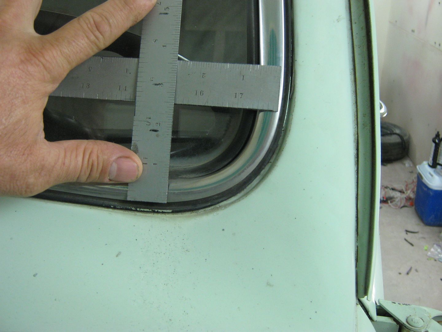
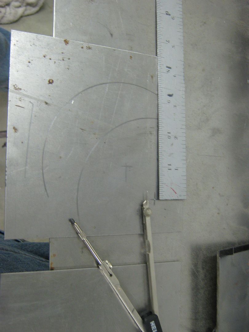
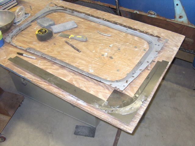
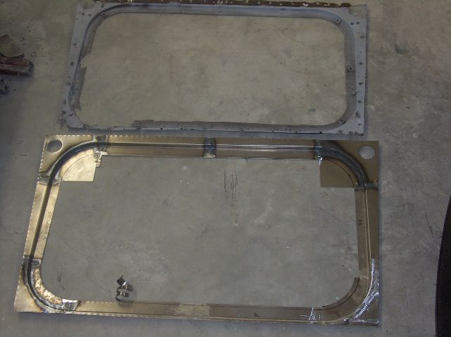
Very likely my "sample" windshield will be different from yours, but this is to show the basics of forming a flange mounted windshield opening with minimal tools. Adjust as needed to suit your application. My windshield is in a 52 F7, and though my w/s is still intact, I'm guessing at about a radius of 2.5"
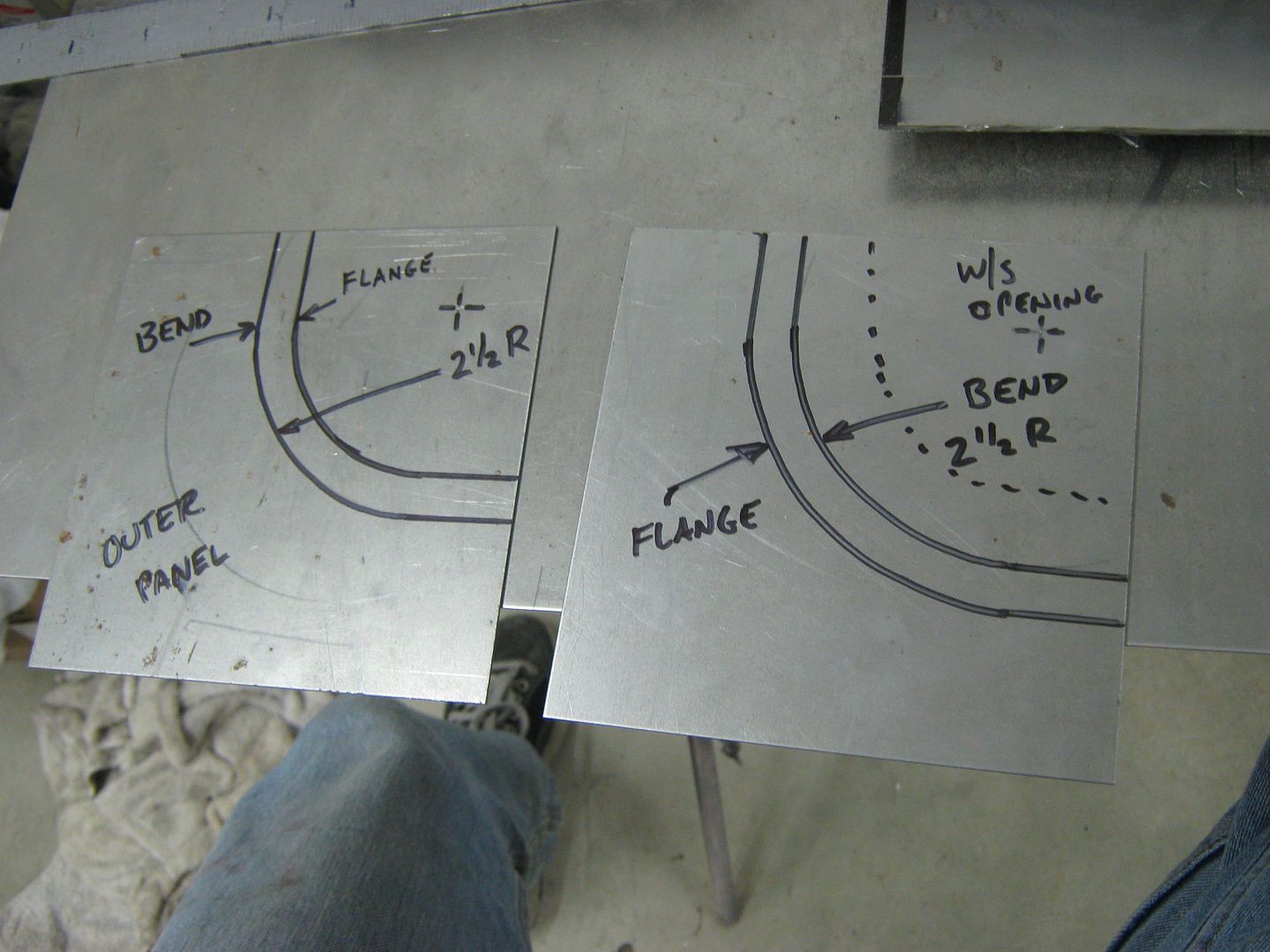
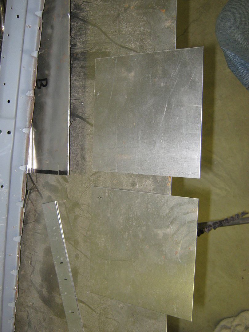
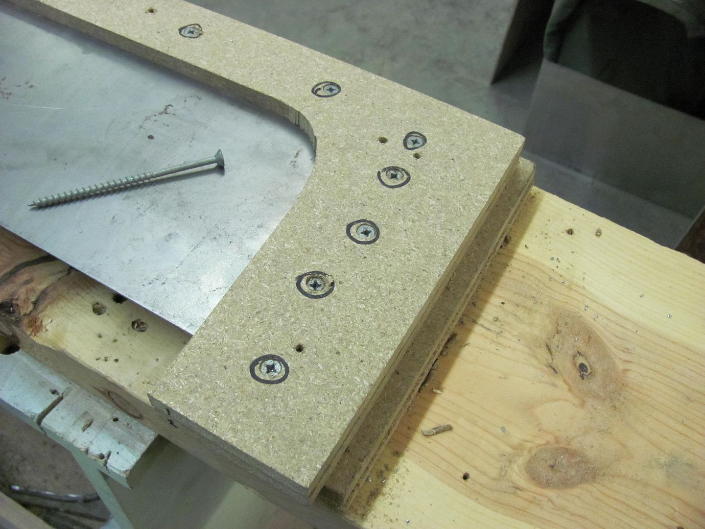
I'll use some 5-1/2" square pieces to make the inner and outer corners. This is 18 ga CRS. A center punch is used to keep the compass point from slipping.
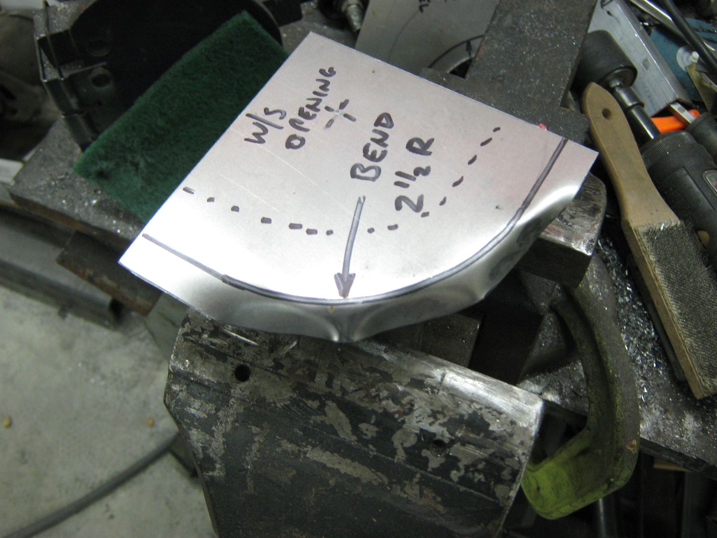
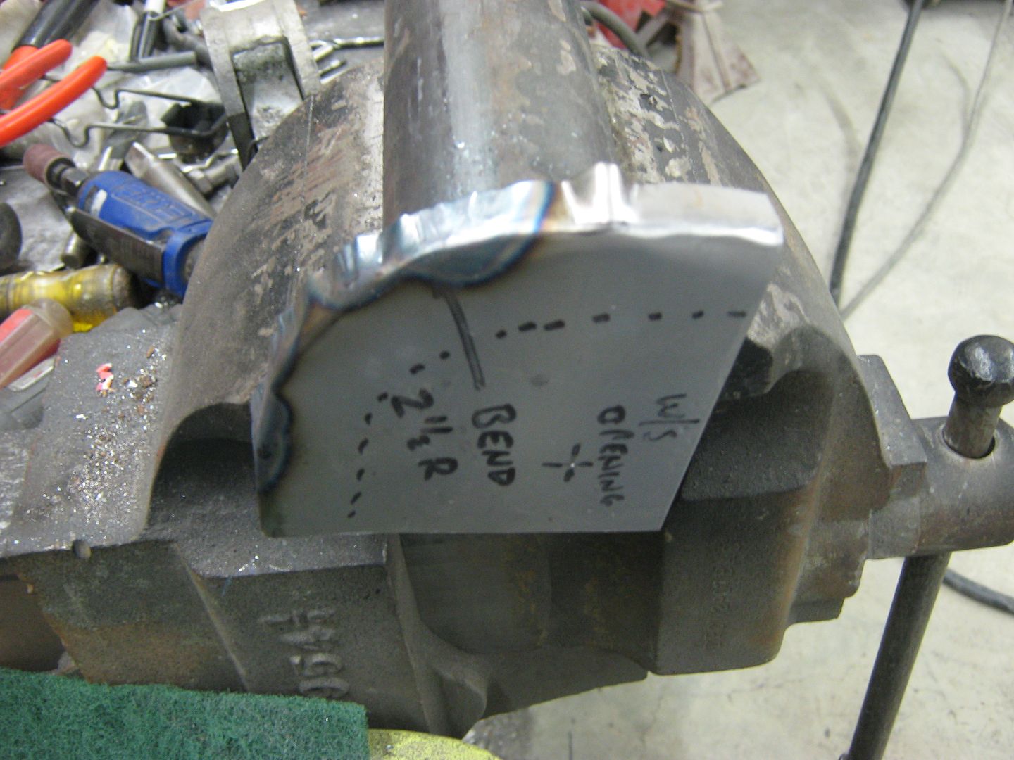
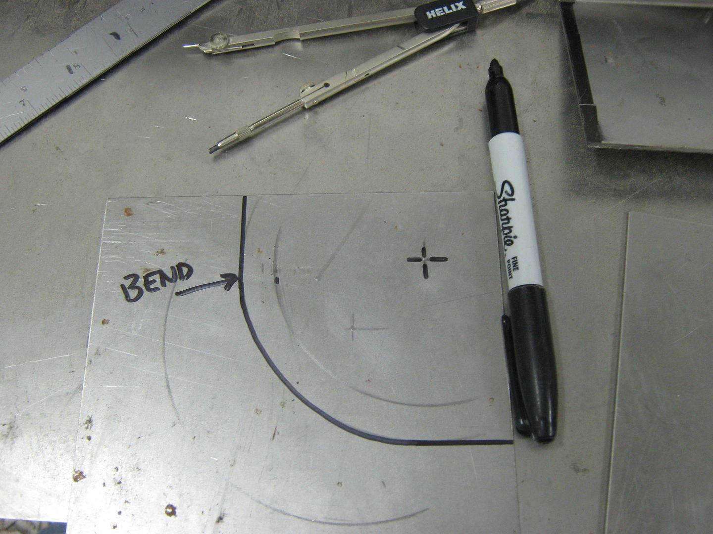
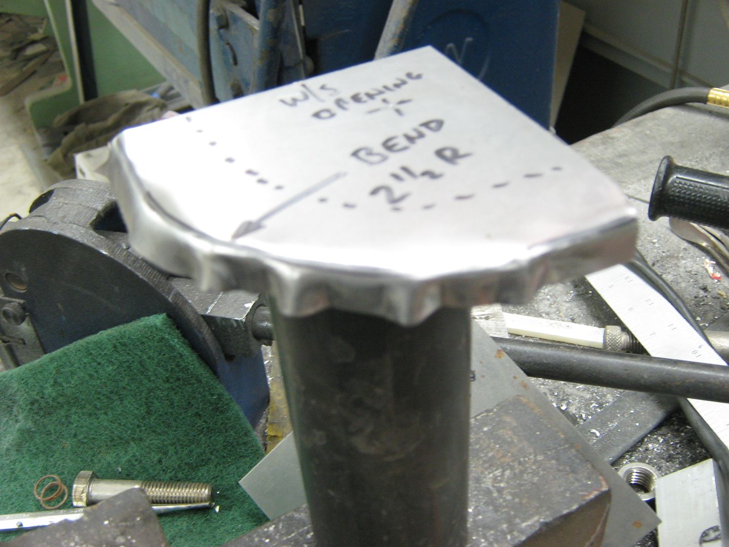
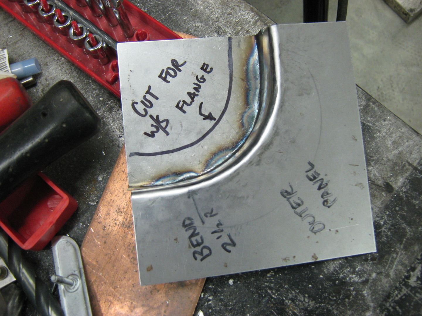
Now mark this out with a sharpie, we'll want to be able to see the mark for awhile amongst all the hammer marks
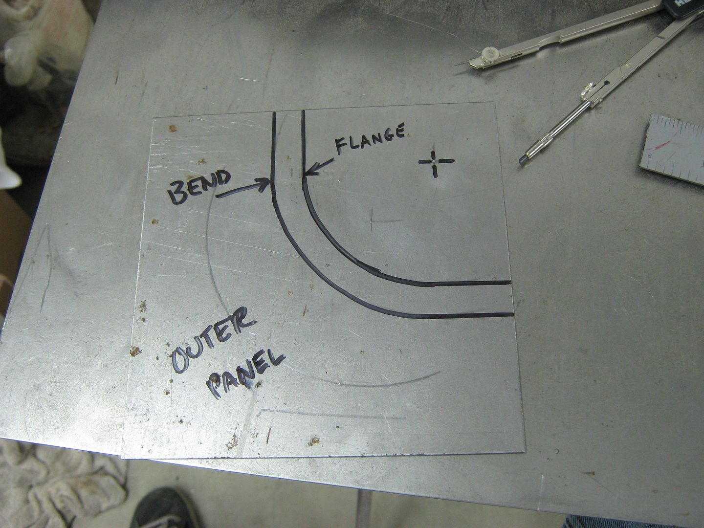
Now take the measurement of the depth of the windshield mounting flange. If it sets back from the outer edge say, 3/4", I'd make the flanges on each of these corner repairs 1/2" to allow some extra for trimming. Too much extra will make for extra work, so keep it within reason
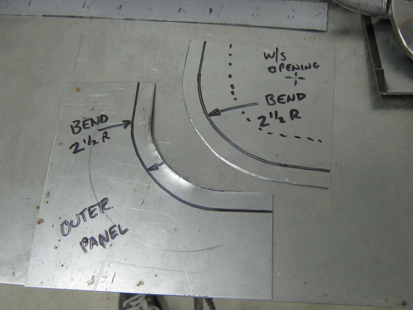
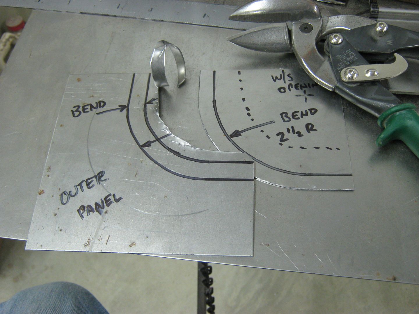
Now repeat for the other piece.
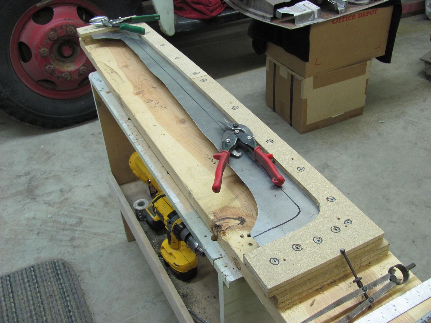
When trimming the excess of an inside corner with tin snips, you'll find multiple cuts will help you to get rid of the bulk so the final cut is pretty accurate. Their capacity rating is for a 1/4" wide cut only, so try to limit each pass to 1/4" wide for best results.
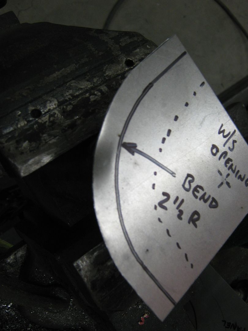
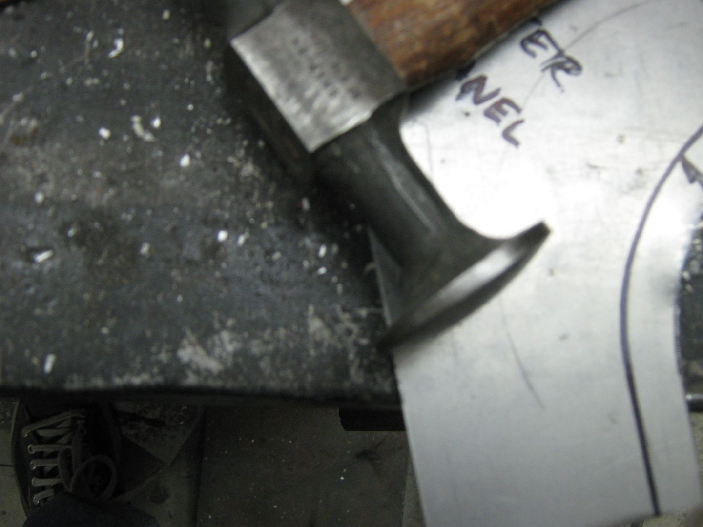
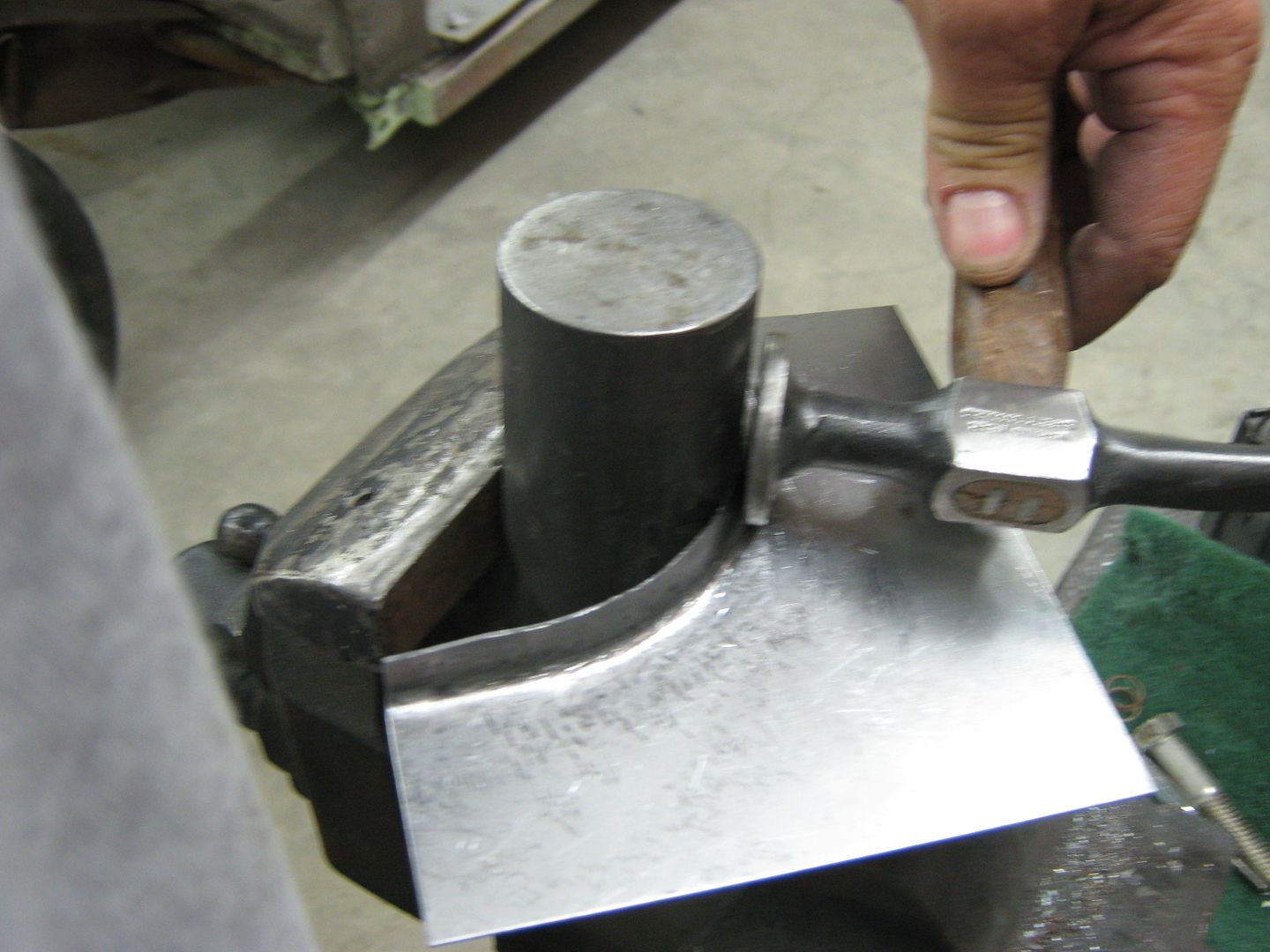
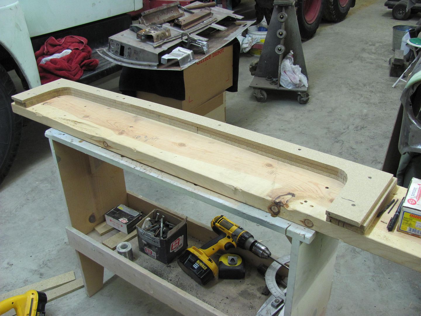
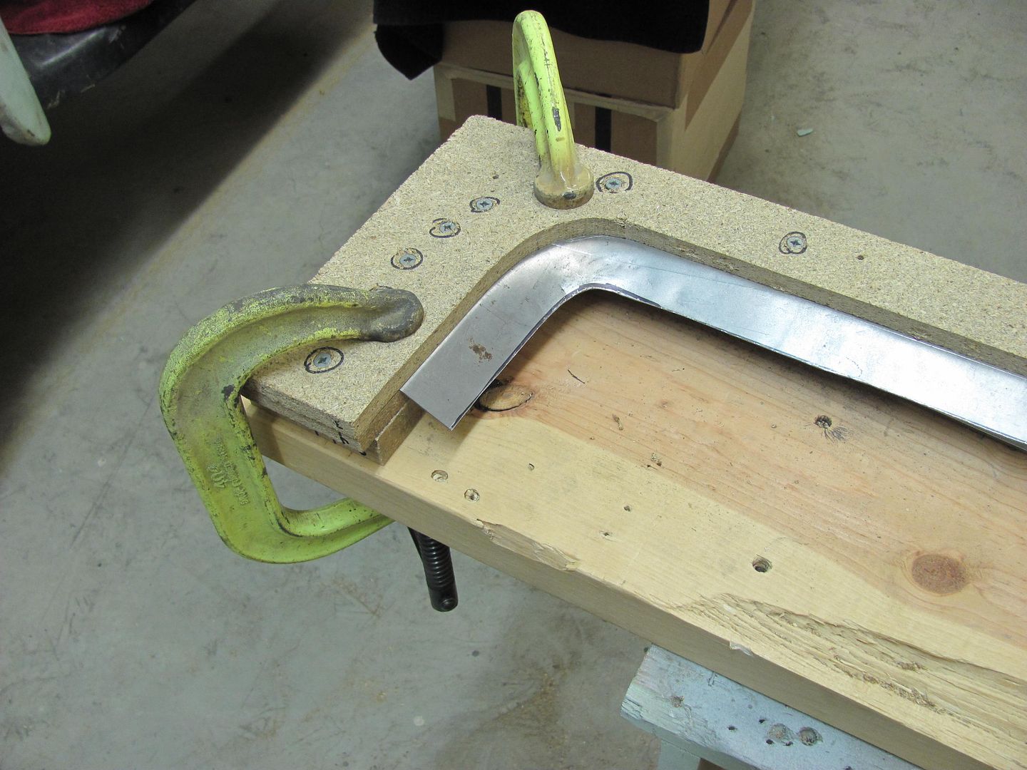
Here's my 2" dia hammerform I was speaking of before. As technical as this stuff is you can use whatever is handy and works.

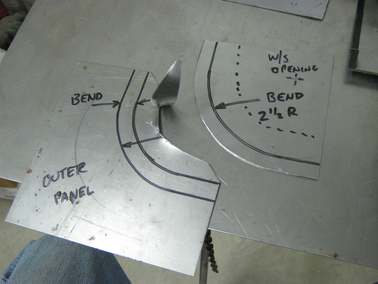
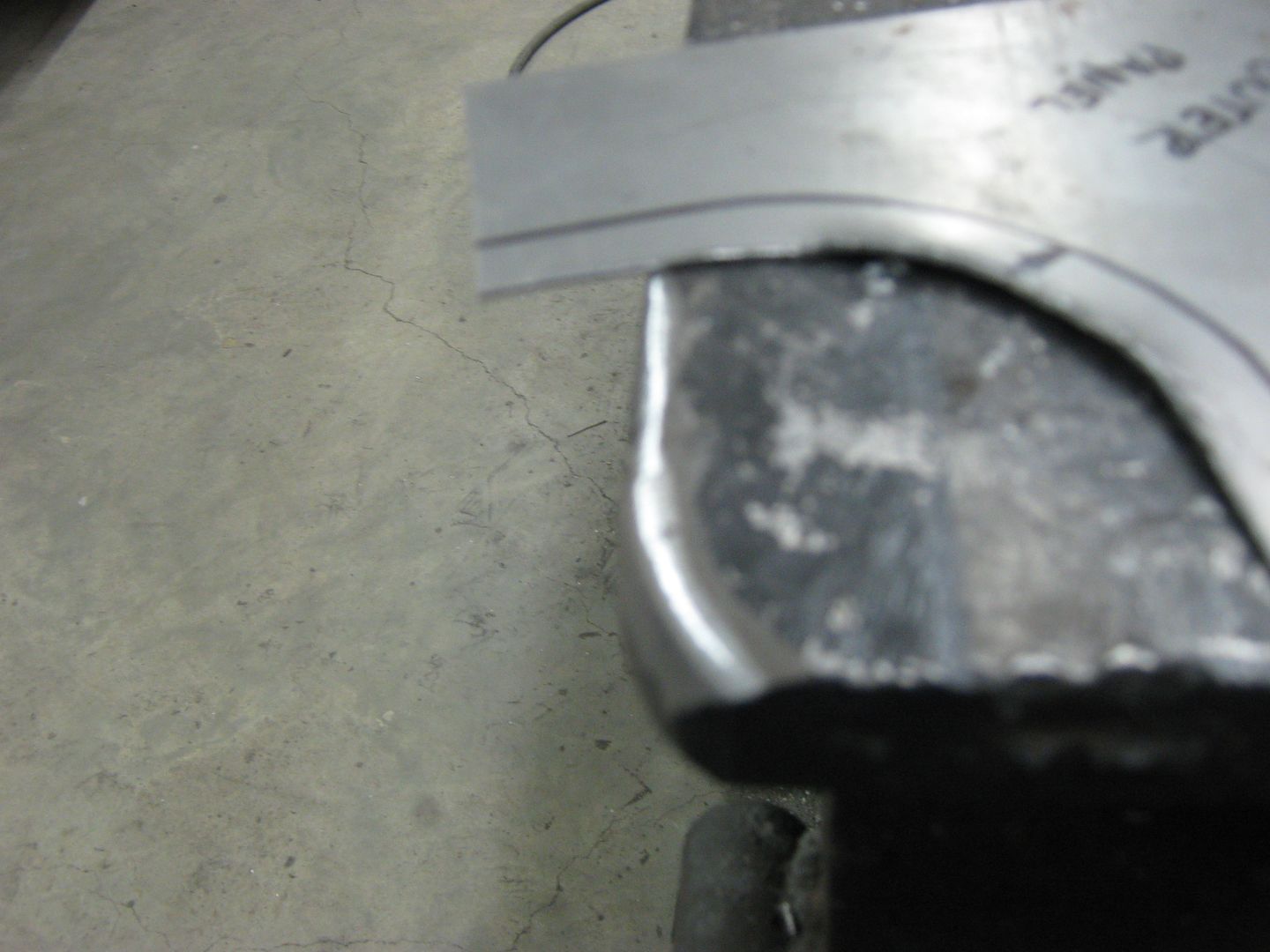
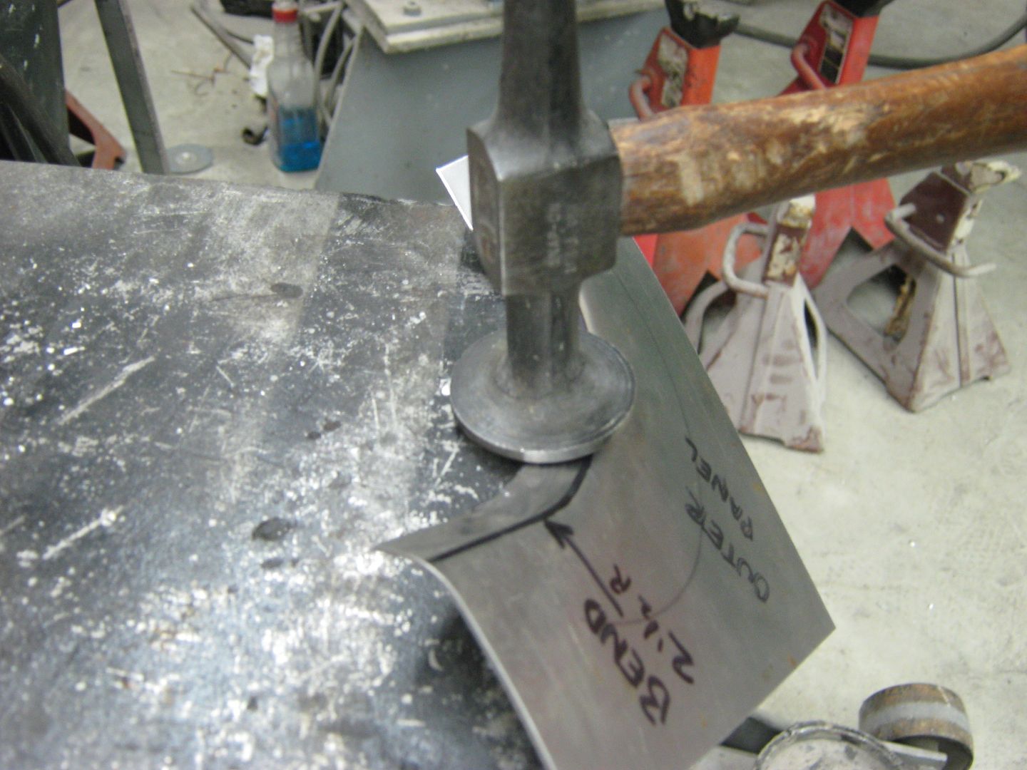
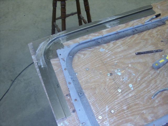
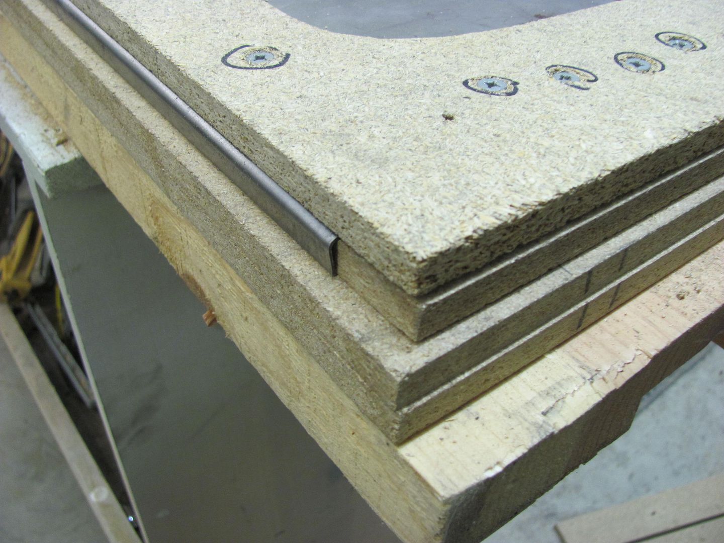
I keep the line up top where I can see what's going on. The first tap with the hammer will show if you are off from your bend line, as you can see. This will show where you are so you can readjust your placement with the next tap.
Looking at the above picture, you can see that the length of our bend line is shorter than the outer perimeter of the flange it is going to form. In essence, once you try to make a 90 degree bend, this excess metal will have a tendency to push the outer corners up.
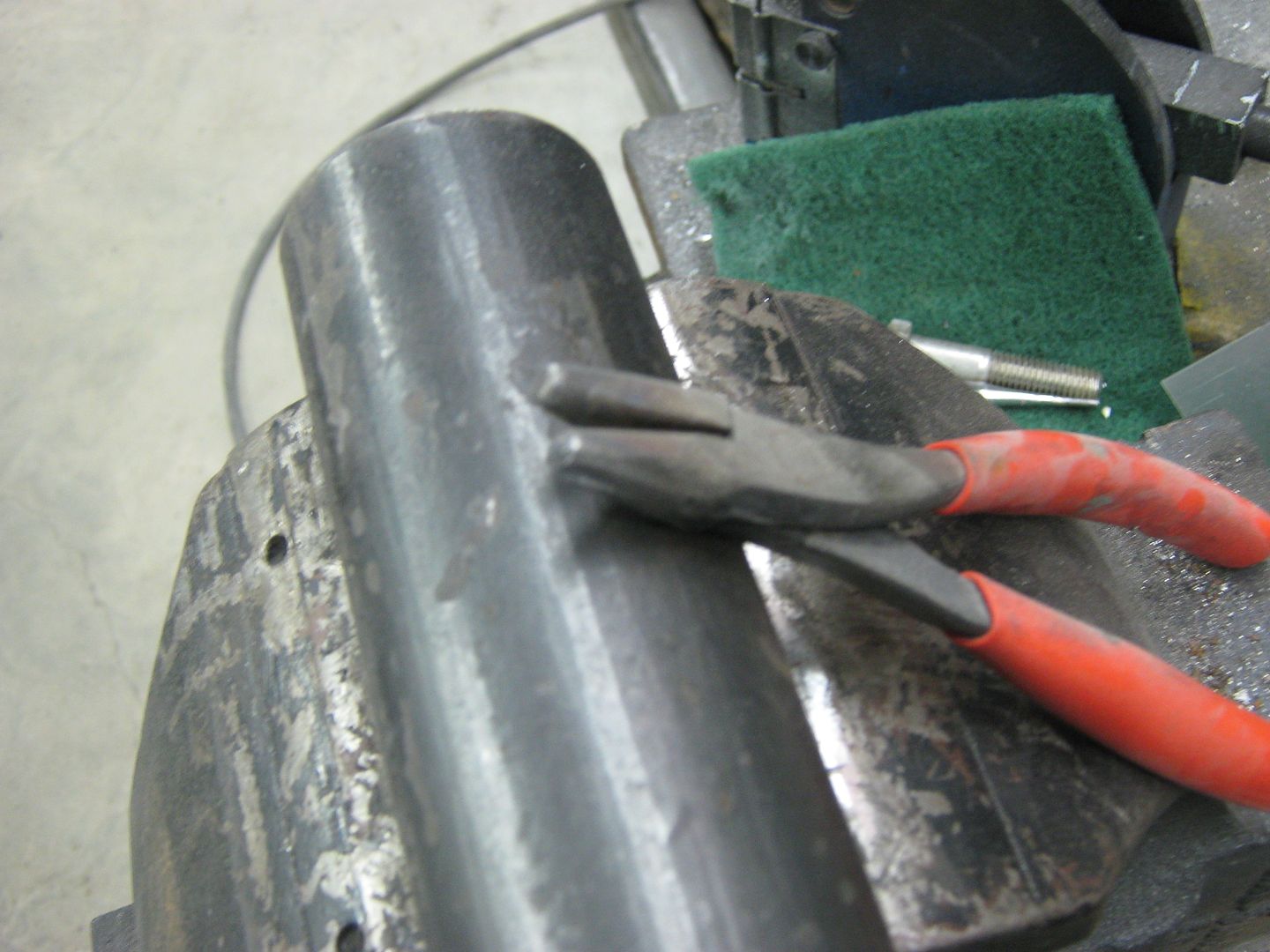
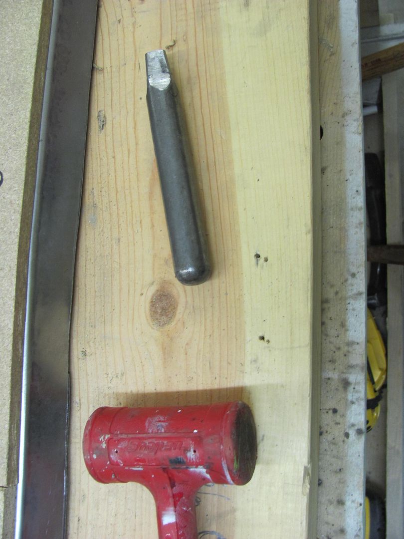
....so we'll need some shrinking of the flange edge to bring things flat again. We'll use what's called a "tucking tool", as those shrinker-stretcher machines don't play well with a tight radius. Here I have made a tucking tool out of a large pair of needle nose I never used for anything else. Please note that all sharp edges of the pliers have been rounded off to prevent cutting into the metal.
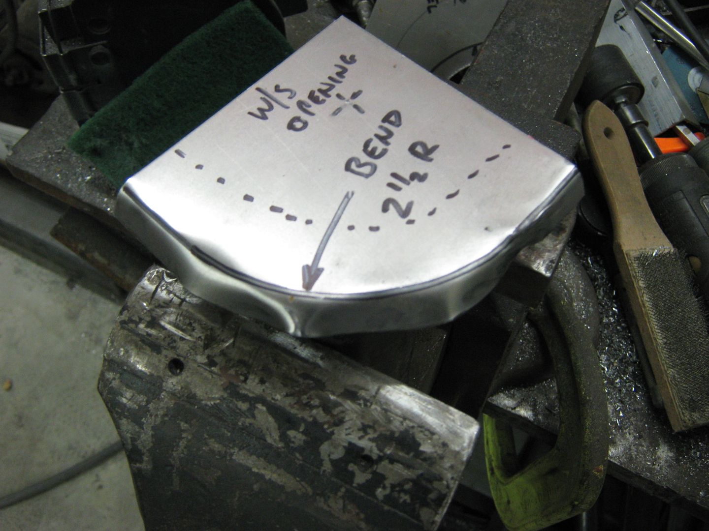
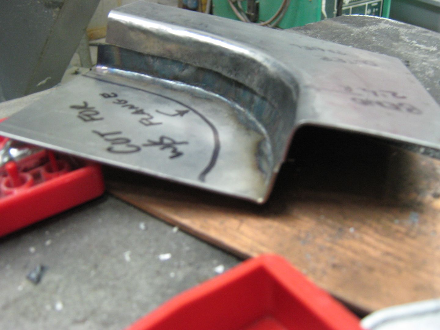
After using the tool to make some "tucks", or gathering up the excess, the object is to heat up the high spot on one of the tucks, place the two lower edges of the tuck so they are resting against your rounded "anvil", and using a flat hammer, tap the high spot back into itself (flatten it out). Repeat as necessary on all the tucks and add as many tucks as needed until the panel flange is bent to the degree you want, and the panel is flat across.
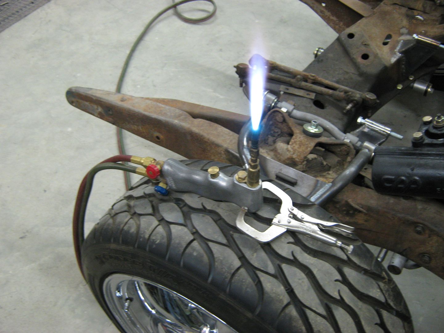
If you're working by yourself, be sure to have a good, secure means to hold your heating device, like a BFG tire.
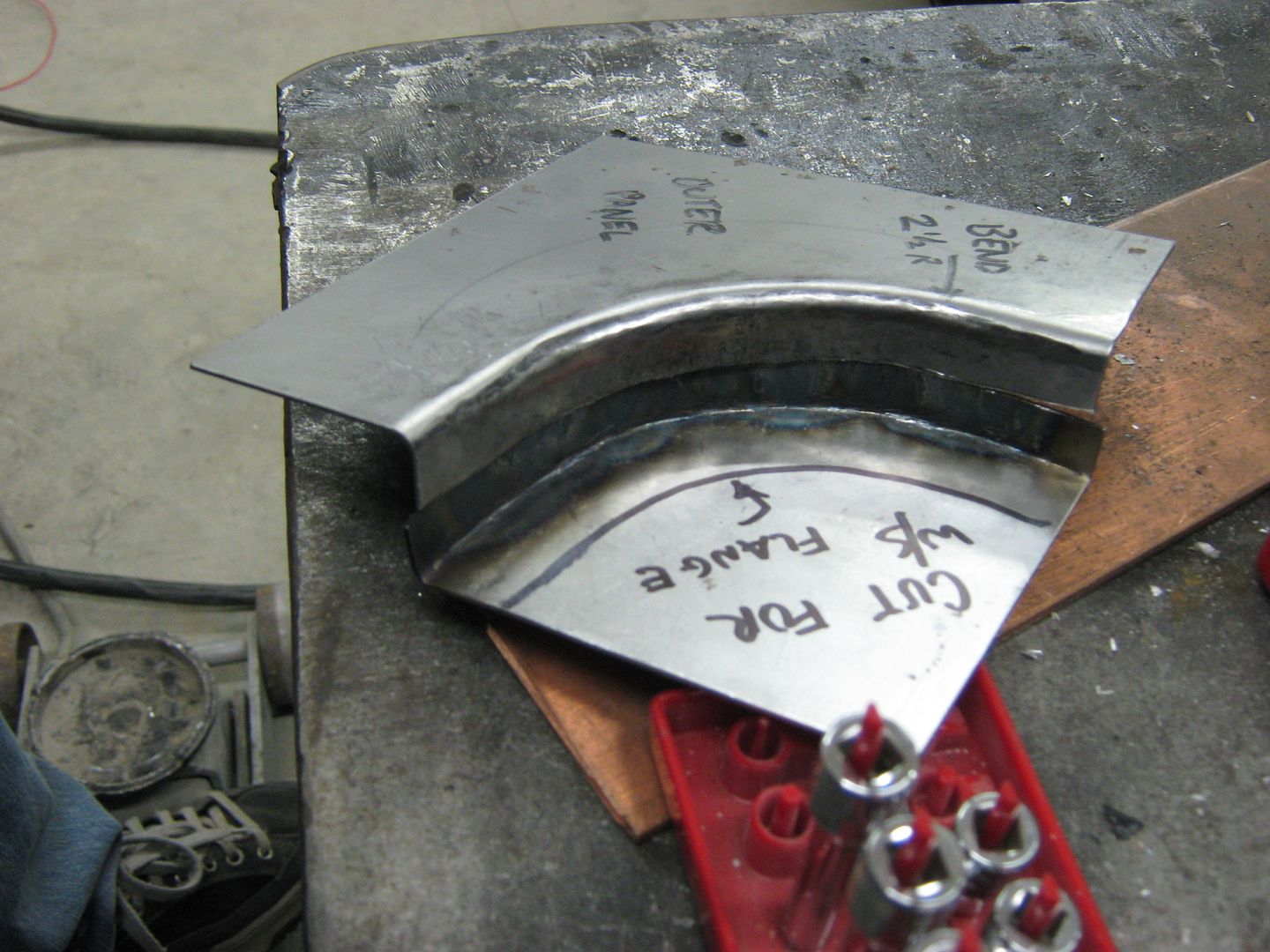
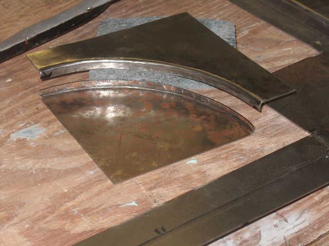
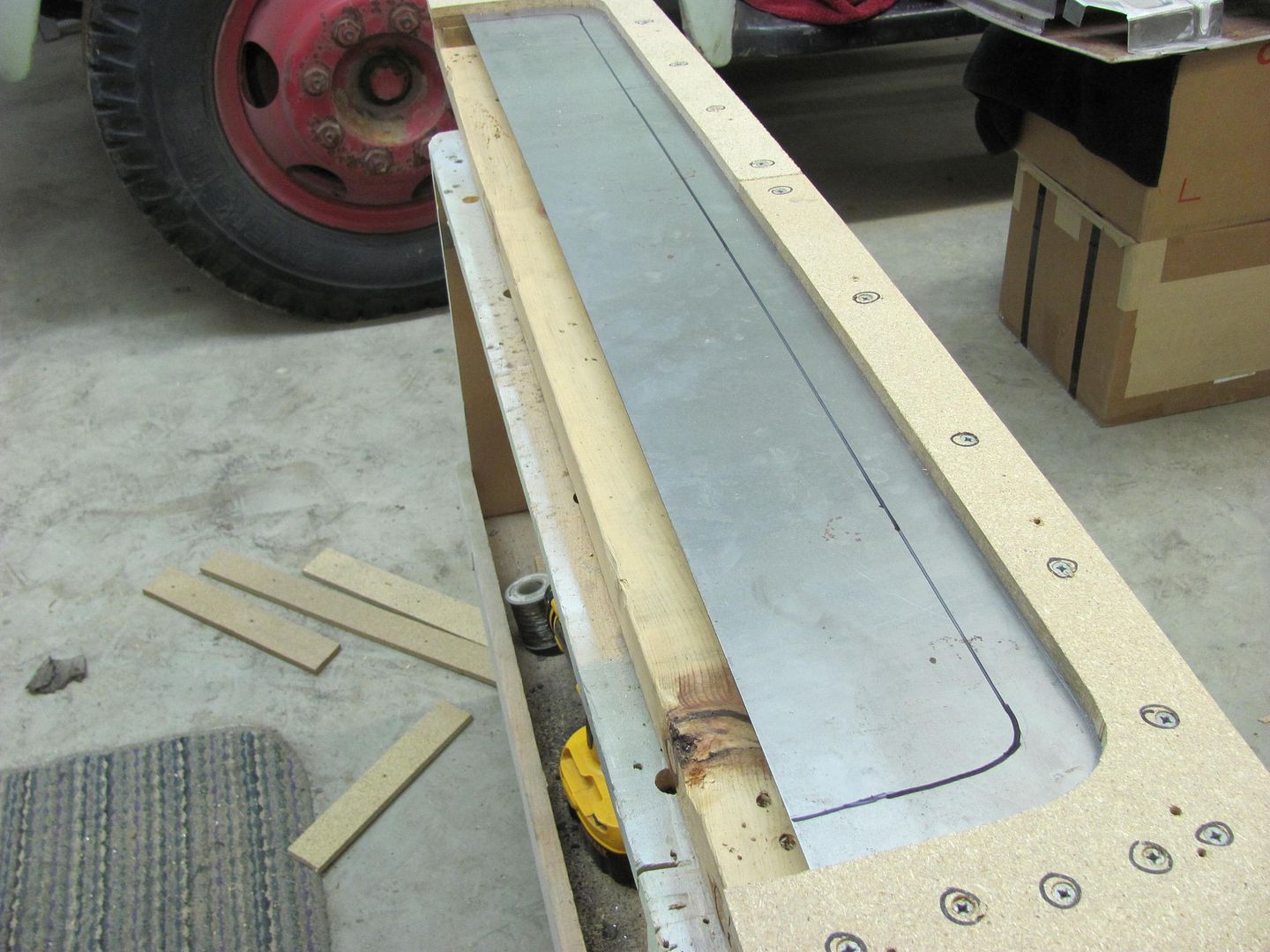
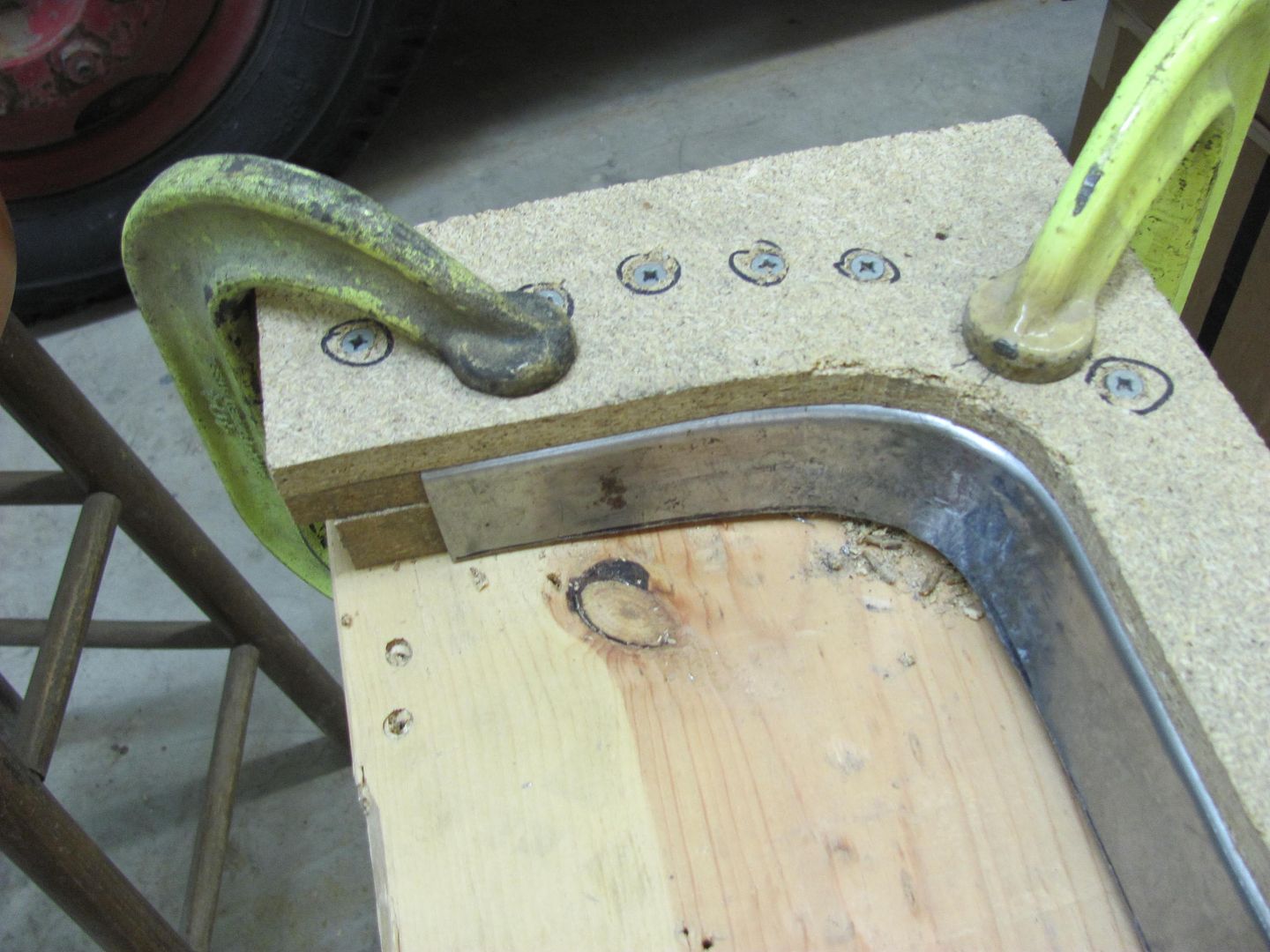
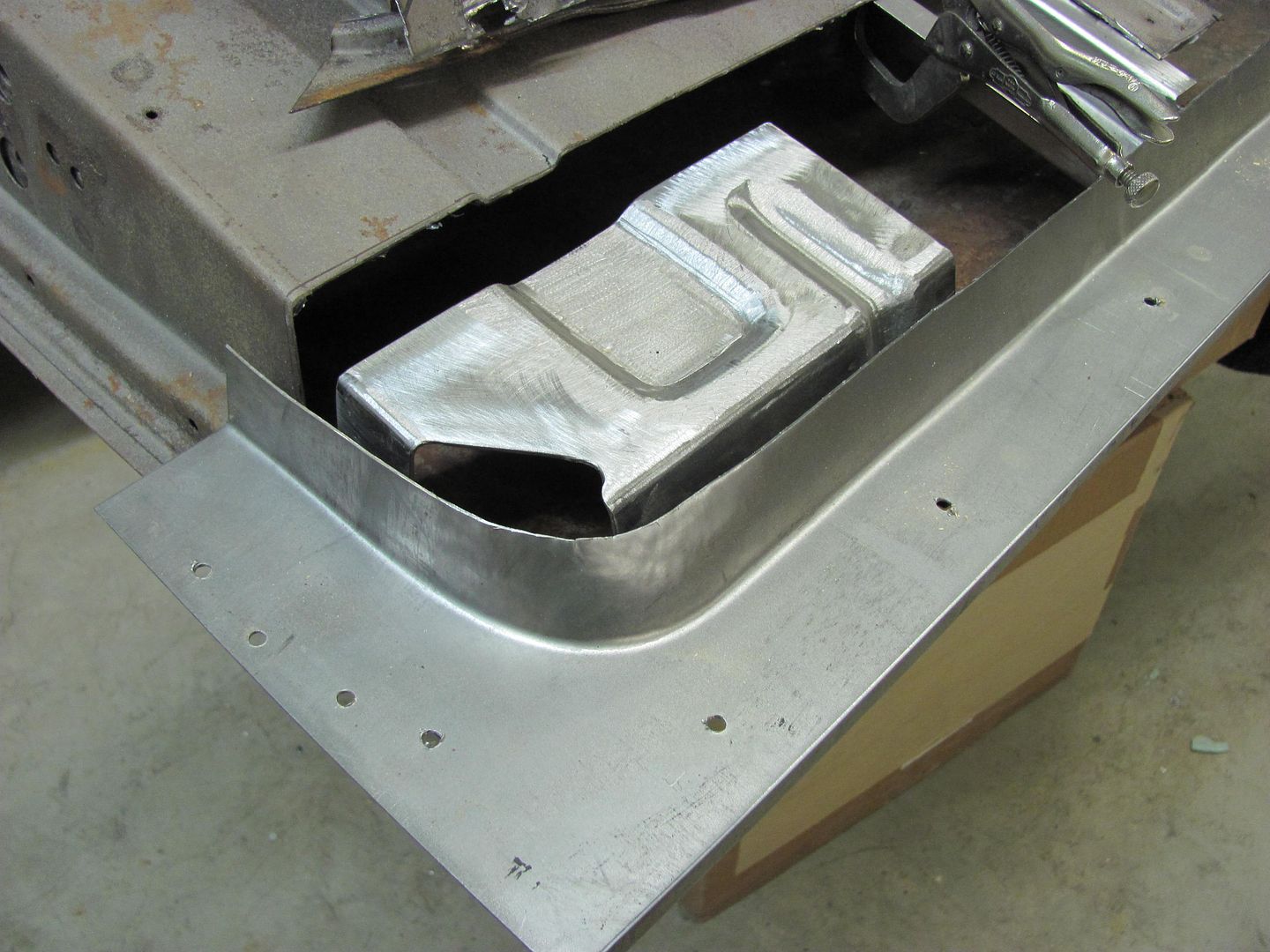
Much better than before, now for the outer piece. This has a slight radius, so I'll do some more grinding on the welding table to provide one:
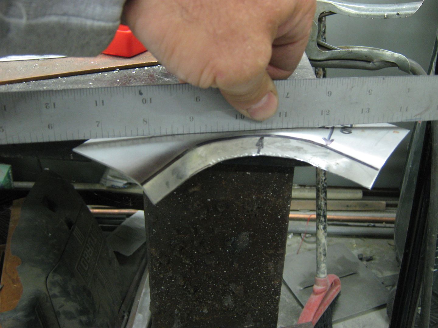
As before, the bend line is of different length than the outer flange perimeter. Here the outer dimension is shorter, so it will have a tendency to pull the panel downward as the bend occurs. To get rid of this issue, we will need to stretch the metal towards the edge of the flange, and a slightly crowned hammer will help out.
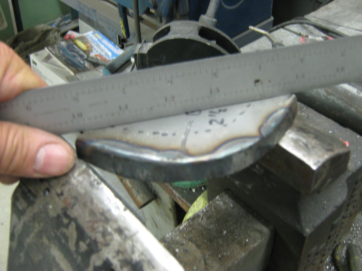
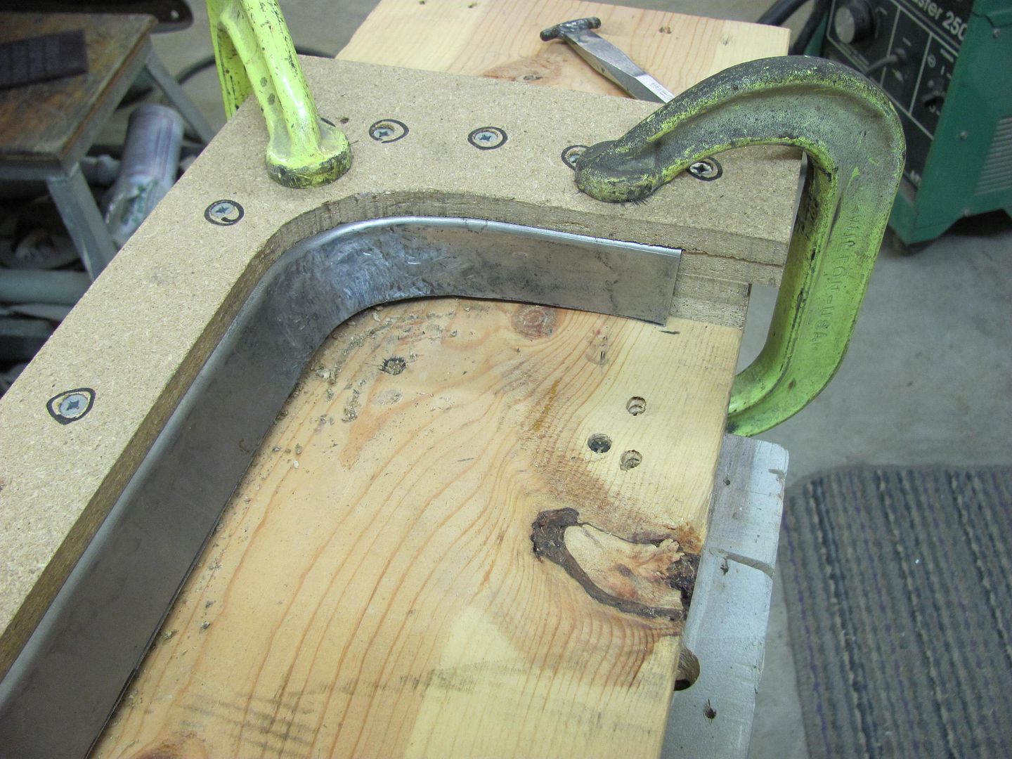
Place the flange on a flat surface and using the hammer, work the area, especially the outer perimeter where it is shorter, this needs more stretching. <br />
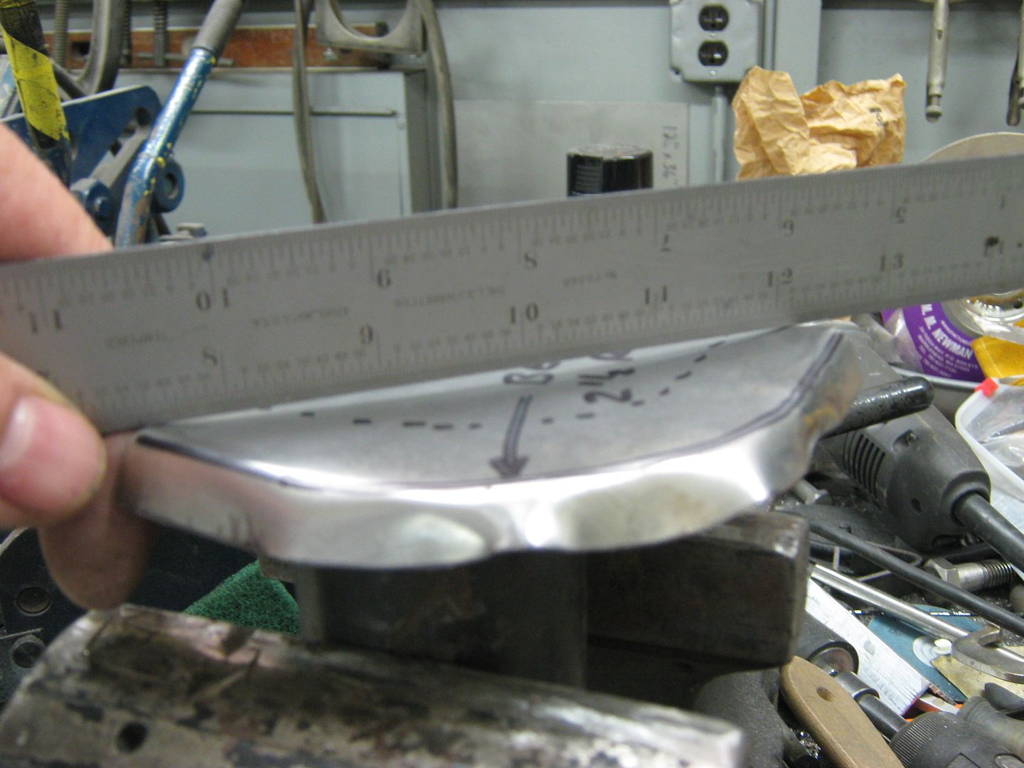
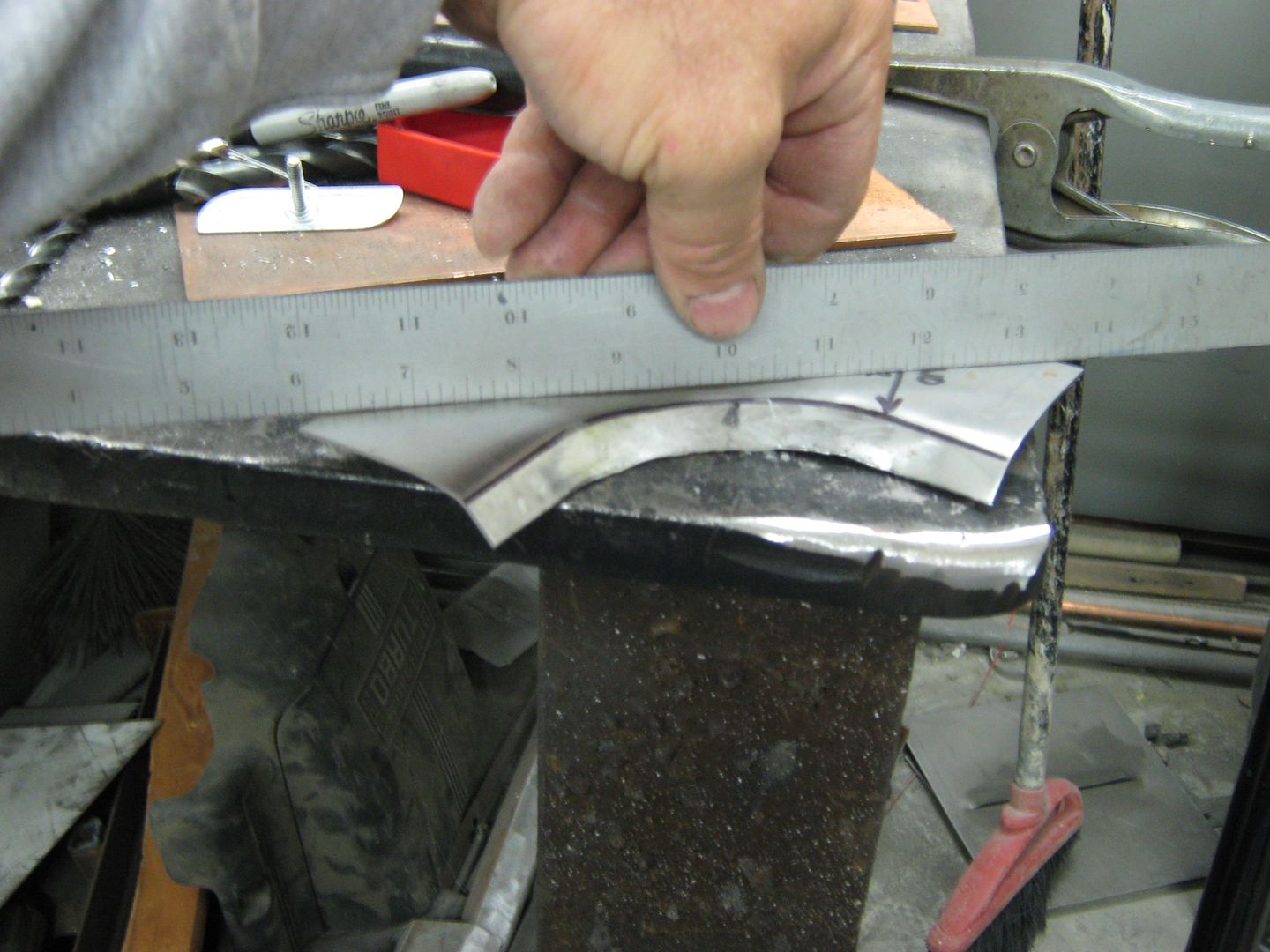
It doesn't take long to notice an improvement. Keep working as needed until you have the correct bend you're looking for, and the section is straight across, if that's what you need..
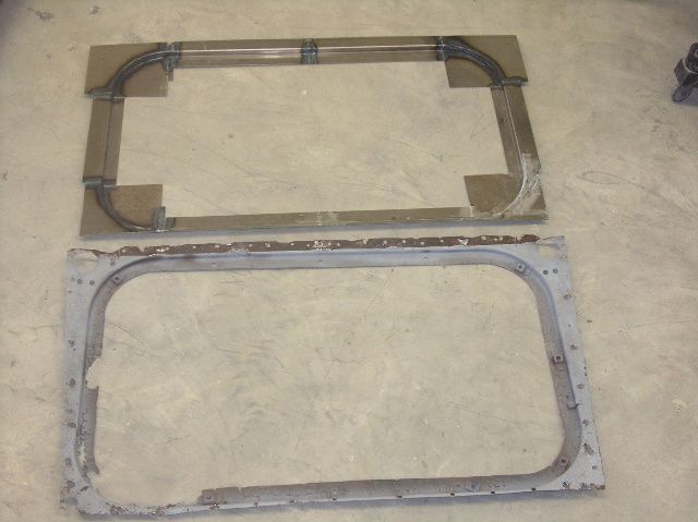
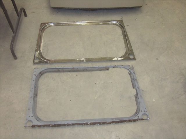
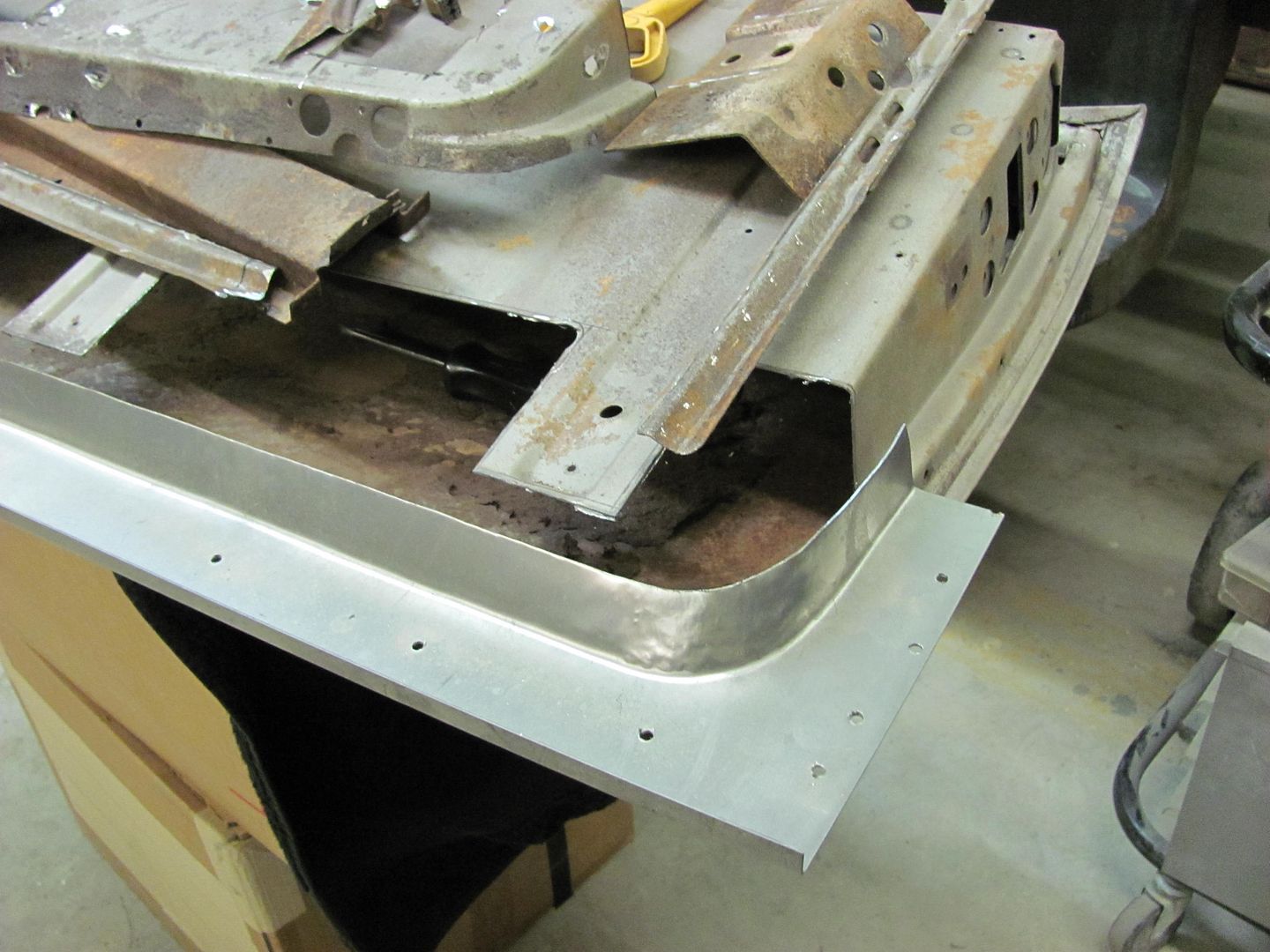
Here I'll normally trim one flange to a nice straight cut, position the other so you have your correct offset, and scribe and trim the other. Weld together, Dress (grind) the welds, and install.


 Reply With Quote
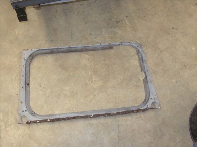

's Avatar")


