Just joined? Please introduce yourself.
Results 1 to 8 of 8

Thread: Trifive chassis designs crossmember fwd of the rearend with drive line loop and exhaust cutouts

  1. #1
    Registered Member rockytopper R.I.P 5-13-2017's Avatar
    Join Date
    Sep 2013

    Member #:1884
    Location
    Covington Texas
    Posts
    1,039

    Trifive chassis designs crossmember fwd of the rearend with drive line loop and exhaust cutouts

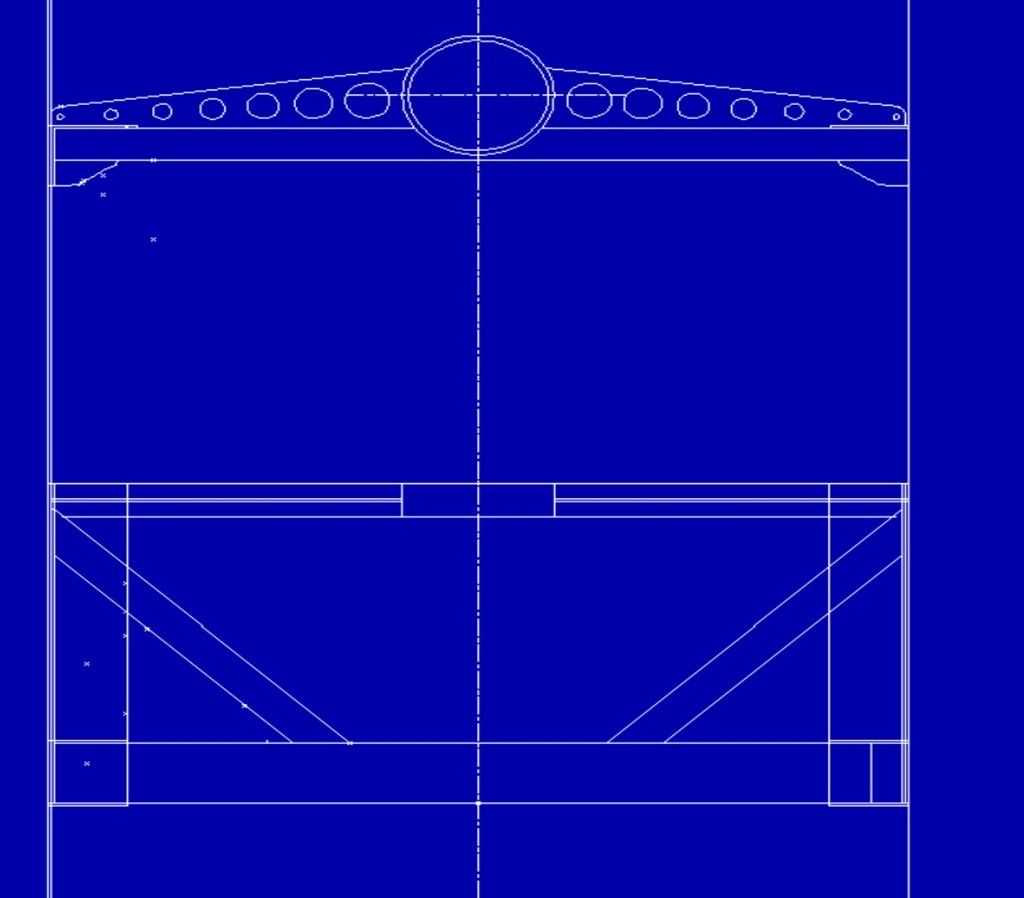
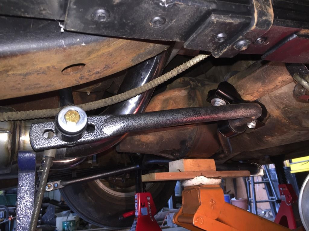
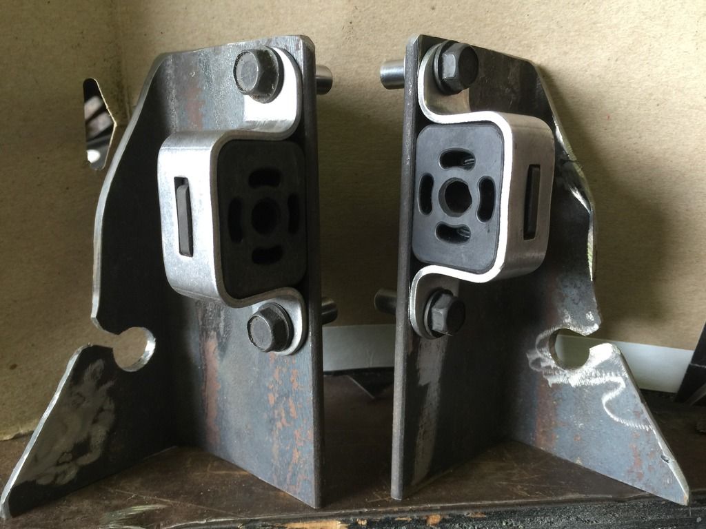
    I have been looking at my chassis design before my nomad ships off to paint jail. I have posted a link to C'nuts site for discussion. I am considering adding a cross member fwd of the rearend as he has the AM version if you will. I currently have a set of brackets designed that hang the exhaust and also mount the e-brake cables. Looking at the sway bar design I have I am also seeing opportunity to incorporate an attachment for it directly to the new cross member everything seems to merge at that location directly behind the body mount. I'm also thinking it is a good place to add support across the frame at the fwd spring mounts on my stock frame. Anyhow a few questions.

    1. How much droop do you design in the loop below the drive shaft for clearance?
    2. How much ground clearance is at the loop?
    3. I assume the rear has to be dropped to pull a drive shaft in the AM design?

    If so I would like to design a top loop in mine like fatman frame and have the lower center section un bolt so I could drop it to replace drive shaft.

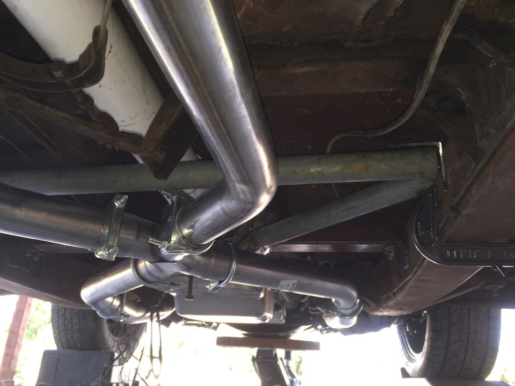
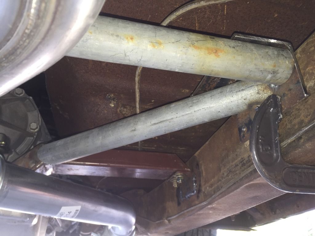
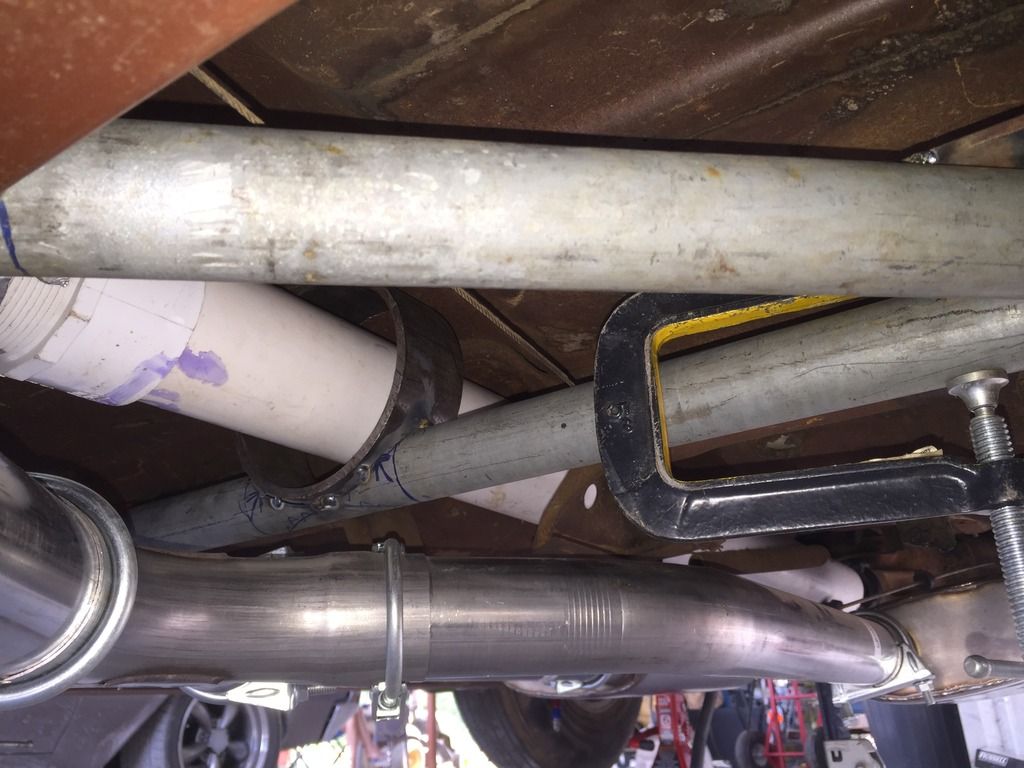
    I have also included a few pictures of my center cross member I pretty much got it figured out. I'm going to extend the 3x3 angle I have attached to the drive shaft loop tubing and tie it to trans cross members along the frame rails and remove my current angles that are supporting the trans cross member this will make it much more rigid. The center section will be bolted in along the rail 16 inches and can be dropped to replace a trans.


    Thanks in advance Rocky

    http://www.classicedgedesigns.com/projects.html


    Last edited by rockytopper R.I.P 5-13-2017; 08-15-2016 at 11:36 AM.

  2. #2
    Registered Member NickP's Avatar
    Join Date
    Mar 2012

    Member #:1653
    Location
    De Queen, AR
    Posts
    4,157

  3. #3
    Registered Member rockytopper R.I.P 5-13-2017's Avatar
    Join Date
    Sep 2013

    Member #:1884
    Location
    Covington Texas
    Posts
    1,039
    Nick do you know the answers to these?
    1. How much droop do you design in the loop below the drive shaft for clearance?
    2. How much ground clearance is at the loop? I assume you posted the AM crossmember specs and it indicates that their loop sticks down 1.75 inches below the frame rails is that correct?

    3. I assume the rear has to be dropped to pull a drive shaft in the AM chassis design? Is this correct?

    Thanks
    Rocky

  4. #4
    Registered Member NickP's Avatar
    Join Date
    Mar 2012

    Member #:1653
    Location
    De Queen, AR
    Posts
    4,157
    Quote Originally Posted by rockytopper View Post
    Nick do you know the answers to these?
    1. How much droop do you design in the loop below the drive shaft for clearance?
    2. How much ground clearance is at the loop? I assume you posted the AM crossmember specs and it indicates that their loop sticks down 1.75 inches below the frame rails is that correct?

    3. I assume the rear has to be dropped to pull a drive shaft in the AM chassis design? Is this correct?

    Thanks
    Rocky
    The sketch, is how AME does their chassis, all I did is add the task specific. Distance to ground is dependent upon many things, tires setup of suspension etc.. If all you have is the rear loop, be it a half loop or full loop, disassembling the U-Joint at the rear is step one. Will it slide back and clear, yes but only far enough to pull it out the front. Having said that, with the center X-Member and two other 2x4 loops it's a bit more tedious.

  5. #5
    Registered Member
    Join Date
    Apr 2012

    Member #:571
    Posts
    4,672
    rocky, the loop needs to clear the driveshaft with some moderate clearance when the suspension is at the limit of travel in both compression and extension. On your leaf spring setup, that's controlled in compression by the rubber bumpers mounted to the axle that contact the frame. In extension, that's controlled by the length and mounting of the shock unless the leaf spring itself restricts the travel.

    If you have all your parts, you may be able to determine what the max travel at the rear u-joint is.

    The final numbers will depend on your axle. The pinion on a Ford 9" is lower than most, and the pinion on a 12 bolt Chevy is higher than most. Stock axle and most others in between.

    You don't want that driveshaft to EVER hit the loop while connected up to the drivetrain, even if it's when you're working the car.
    Last edited by Rick_L; 08-17-2016 at 04:14 PM.

  6. #6
    Registered Member rockytopper R.I.P 5-13-2017's Avatar
    Join Date
    Sep 2013

    Member #:1884
    Location
    Covington Texas
    Posts
    1,039
    Rick I need to complete the puzzle as you have suggested I believe my numbers are flawed I need to order a real shaft to determine what I am dealing with.

  7. #7
    Registered Member NickP's Avatar
    Join Date
    Mar 2012

    Member #:1653
    Location
    De Queen, AR
    Posts
    4,157
    Rocky do you have the transmission in the vehicle? I know the rear is. Do a string line (taught) from yoke to yoke with the car at the chosen ride height. It doesn't need to be on a lift unless you're like me and when down, can't get up. You can use 2" wide tie down straps to collapse the rear suspension or, if you know the present dimensions draw it up. It's not Rocky Science. ;0

  8. #8
    Registered Member rockytopper R.I.P 5-13-2017's Avatar
    Join Date
    Sep 2013

    Member #:1884
    Location
    Covington Texas
    Posts
    1,039
    I know Nick lol... If you look at the pics you might notice a 3 in pvc pipe. I used it to set my front loop. I didn't start thinking about this until I had already dropped it off the jack stands ready to be transported to the body shop. I jacked the car up and took rough measurements with tires hanging as Rick suggested with my arm only reaching because I did not want to crawl under with jack only. But now it has rained every day and the car is still stuck in my shop so I might just have to put back on the stands. Besides that I need a drive shaft anyway and I'm afraid ground clearance will be an issue with a closed loop on my stock setup. If not I will need to place the loop as close to the shaft as possible using the same heavy walled 6 inch pipe I used in my front loop. Else I am thinking I might just leave the bottom open and use one of these hoops. https://cachassisworks.com/p-129-dri...de-height.aspx

    Or I might just drop the idea out of my head altogether and use the brackets I already fabbed lol... I realized I cannot tie the sway bar directly to the frame with out the swing arm or it would bind the suspension..

    And for the record I do my best work laying on my back on the floor. I suffer from extreme back pain and cannot stand for long periods. And I am to darn tall for most car lifts I have to stay bent over lol....
    Last edited by rockytopper R.I.P 5-13-2017; 08-18-2016 at 07:18 AM.

Posting Permissions

  • You may not post new threads
  • You may not post replies
  • You may not post attachments
  • You may not edit your posts
  •