Just joined? Please introduce yourself.
Results 1 to 5 of 5

Thread: 1955 Fender Eyebrow Replacement

  1. #1
    Registered Member MP&C's Avatar
    Join Date
    Dec 2013

    Member #:2017
    Location
    Southern MD
    Posts
    1,293

    1955 Fender Eyebrow Replacement

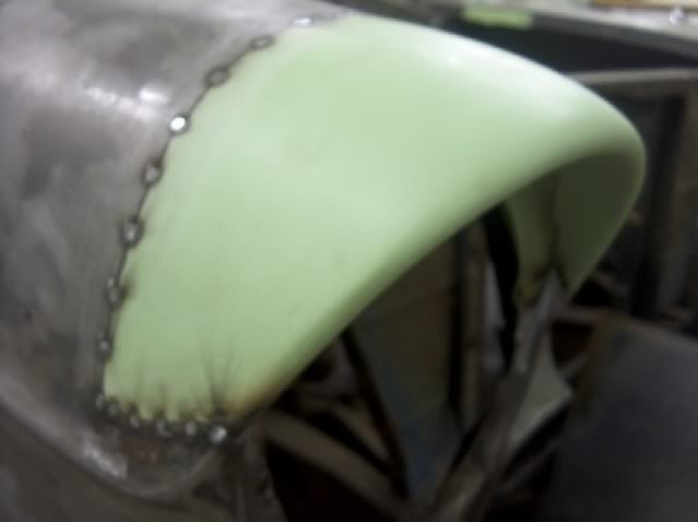
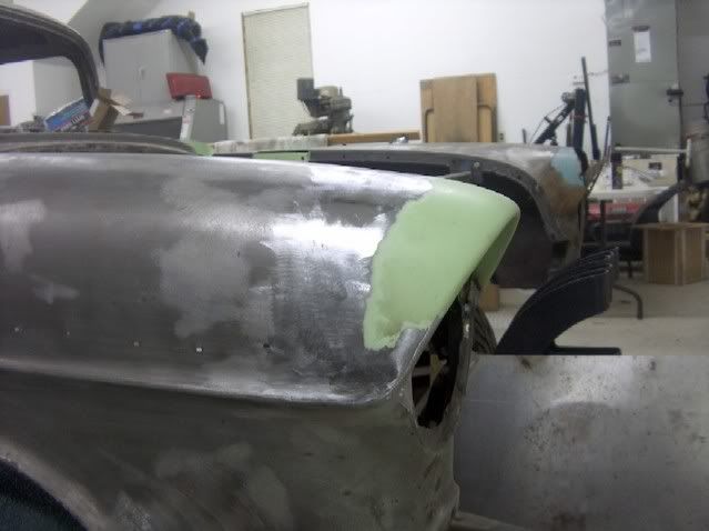
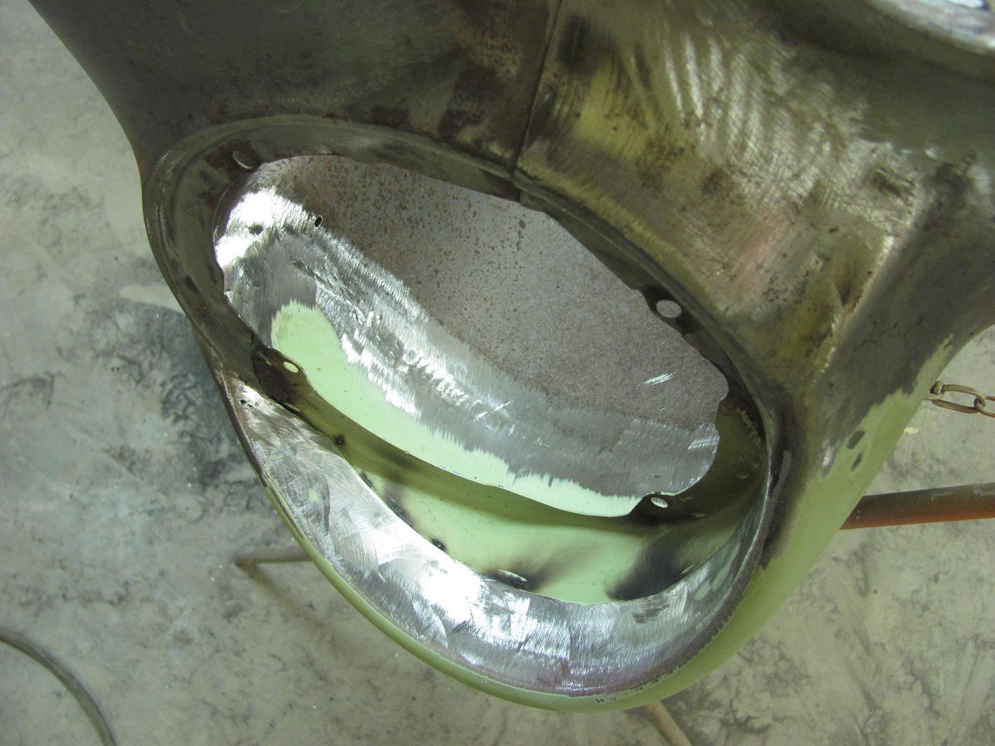
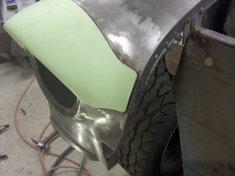
    We got some new eyebrows and they were primed ahead of time to get good coverage under the lapped seam of the headlight ring, so they were ready to go. The stepped flange that the caps come with were trimmed off to permit butt welding. All of the damage seen in this area is from dirt and water thrown forward by the tires, so a flanged seam is the last thing needed here. The fenders had repairs previously done, and the "caps" were slipped over the existing, and held on with one tack weld and a few sheet metal screws. After removal I saw that part of the contour to the inside of the headlight was mashed in so the "cap" would fit better. (thanks for the favor)


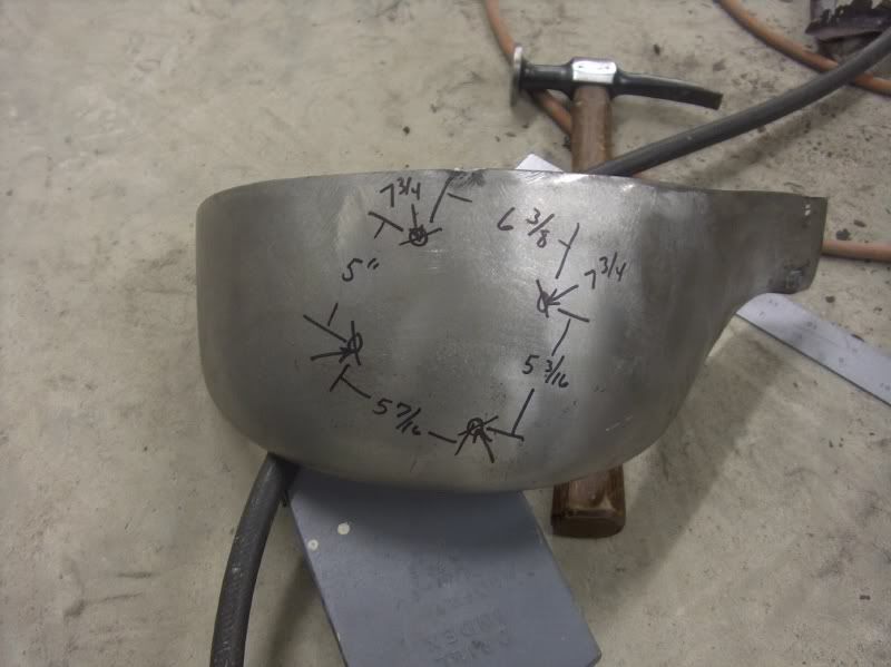
    The headlight mounting ring will be the next thing removed, but first, take some reference measurements on the mounting holes for locating the new one.


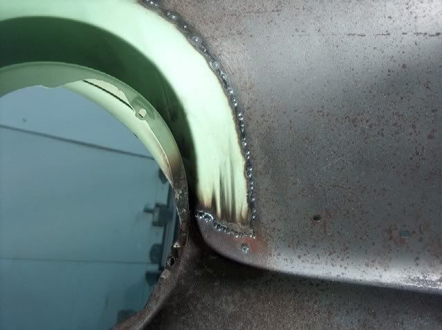
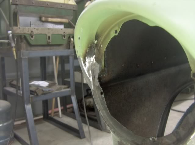
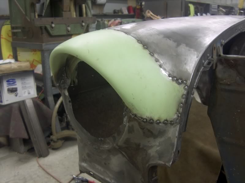
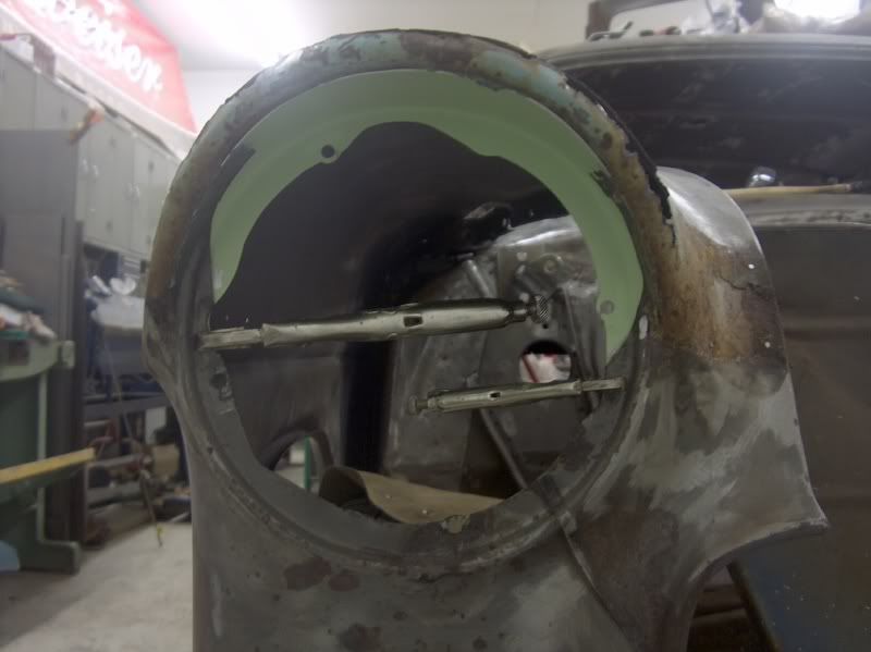
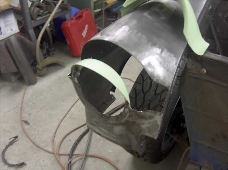
    Measured, clamped in place, and welded on


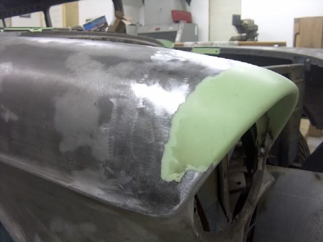
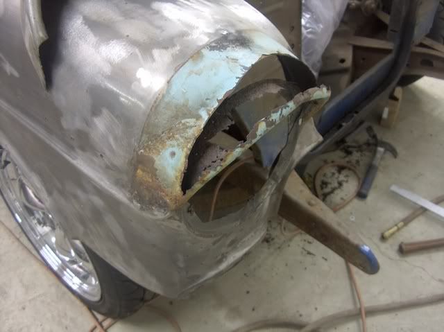
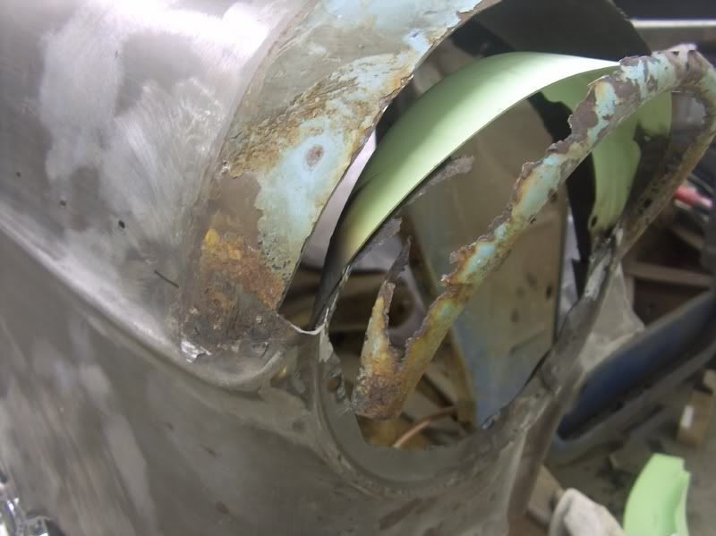
    Next, to trim away some of the leftover eyebrow, so the new eyebrow can be butt welded in place this time around.


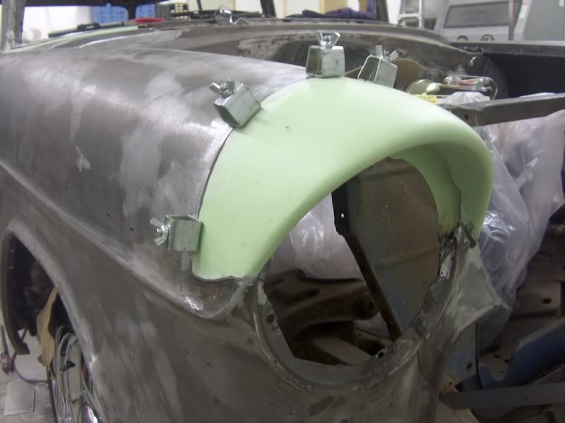
    It was fitted and trimmed, fitted and trimmed. Repeat as necessary.


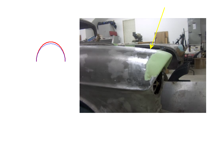
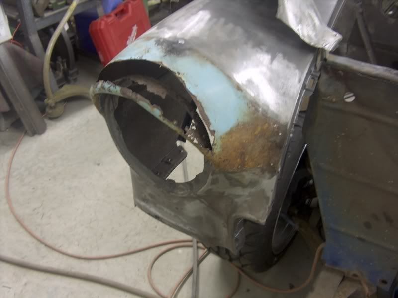
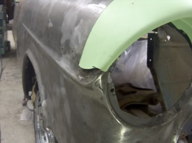
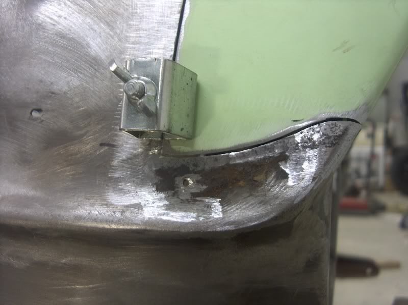
    Hindsight, the vertical cut shown above by the hood opening should have been made farther away from the hood opening. The minimal amount left of the original is prone to movement/pulling as the weld shrinks. Leaving about 1-1/2" of material adjacent to the flange with the vertical weld through the valley would help prevent any movement of the hood opening, so learn from my mistakes and don't cut that part as shown.


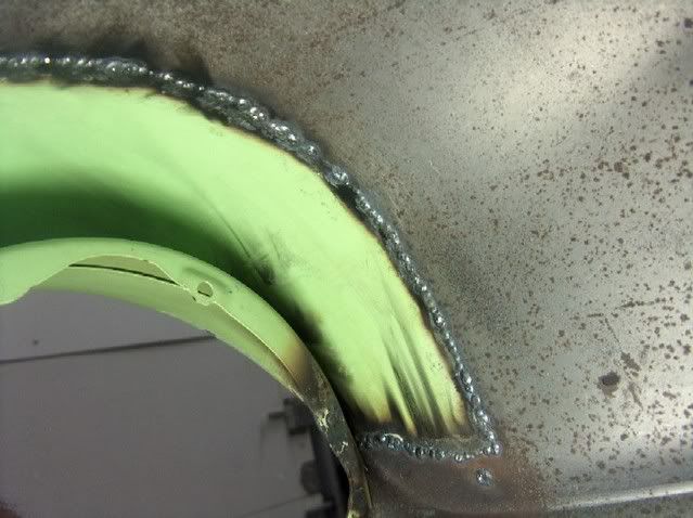
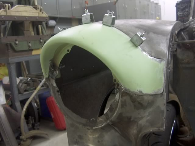
    NOTE: I typically use the butt weld clamps shown below as a clamp for fitment only. Once I begin to tack the panel in place, I move the clamps out of the way so the gaps are minimal.


    The tighter you can get the gaps, the easier it will be to weld, and the less the panel will move on you as the welds shrink.


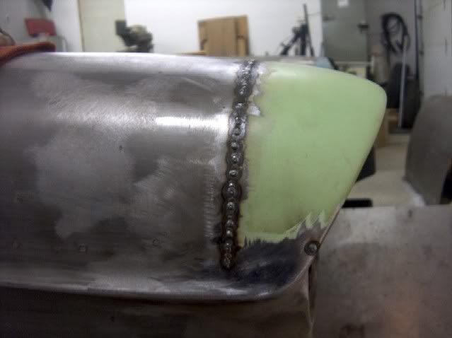
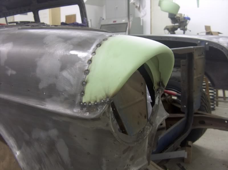
    All tacked in place.


    Last edited by MP&C; 12-28-2013 at 06:25 AM.
    Robert


    MP&C Shop Projects-Metalshaping Tutorials


    Instagram @ mccartney_paint_and_custom


    .

  2. #2
    Registered Member MP&C's Avatar
    Join Date
    Dec 2013

    Member #:2017
    Location
    Southern MD
    Posts
    1,293
    The first tack welds were ground down until the were just above the metal surface to get them out of the way. Then planish with a hammer on the outside, and a dolly on the inside that closely matches the inside radius of the panel. Then I tacked in between these last welds, skipping around, grind, planish, repeat.


    Don't forget to check your welder setup by observing for weld penetration on the back side.


    Continue to grind down the weld "dots" as you go, and planish to keep any shrinking in check.. As the weld cools, it shrinks. Looking at a cross section of the patch panel we have a long arc that stretches from the outside of the fender to the inside. Once we weld along this seam, eventually going from one end to the other, the heat from welding will shrink the weld and area of the HAZ (heat affected zone). In most cases of welding sheet metal panels, any shrinkage from the welding will tend to be more prominant within the center section of the panel, especially one with a low crown. In effect, the original arc shape (red) as the heat from welding shrinks the area, will cause the arc to shorten in length. As the welded ends are locked in place, the result will be a smaller arc (blue) which can be seen as a slight dip (yellow arrow). This is a good example of where planishing will stretch out the weld and HAZ to restore the crown and remove the valley.


    The eyebrow is then plug welded to the upper headlight ring with about 4 equally spaced plug welds. (Shown here after dressing the welds) Also note the welds inside have been ground flush...


    Robert


    MP&C Shop Projects-Metalshaping Tutorials


    Instagram @ mccartney_paint_and_custom


    .

  3. #3
    Registered Member JT56's Avatar
    Join Date
    Mar 2013

    Member #:1608
    Location
    DFW Texas
    Posts
    1,209
    Great Job Robert!

  4. #4
    Banned
    Join Date
    May 2013

    Member #:1708
    Location
    Northern Alberta
    Posts
    109
    wow, very nice work!

  5. #5
    Registered Member MP&C's Avatar
    Join Date
    Dec 2013

    Member #:2017
    Location
    Southern MD
    Posts
    1,293
    Thanks guys!
    Robert


    MP&C Shop Projects-Metalshaping Tutorials


    Instagram @ mccartney_paint_and_custom


    .

Posting Permissions

  • You may not post new threads
  • You may not post replies
  • You may not post attachments
  • You may not edit your posts
  •