


Finally decided to install the fuse block I had built a couple of years ago before it gets to nice out. Once the weather takes a turn for the better I will want to be driving my 55 so I want to get this done now so It doesn't get put off another year.
A couple of years ago I started looking at fuse blocks to replace the original one. I only needed the fuse block, not a complete wiring harness as I had replaced all the wiring with original style harnesses back in the mid 80's when I did the first frame off rebuild. I didn't find any that I liked so I eventually ended up building my own with the 4 circuit add on fuse blocks that can be hooked to each other. I already had one of this style added next to the original when I added my power seats, back up lights, radio and a cigarette lighter style power tap to my console.
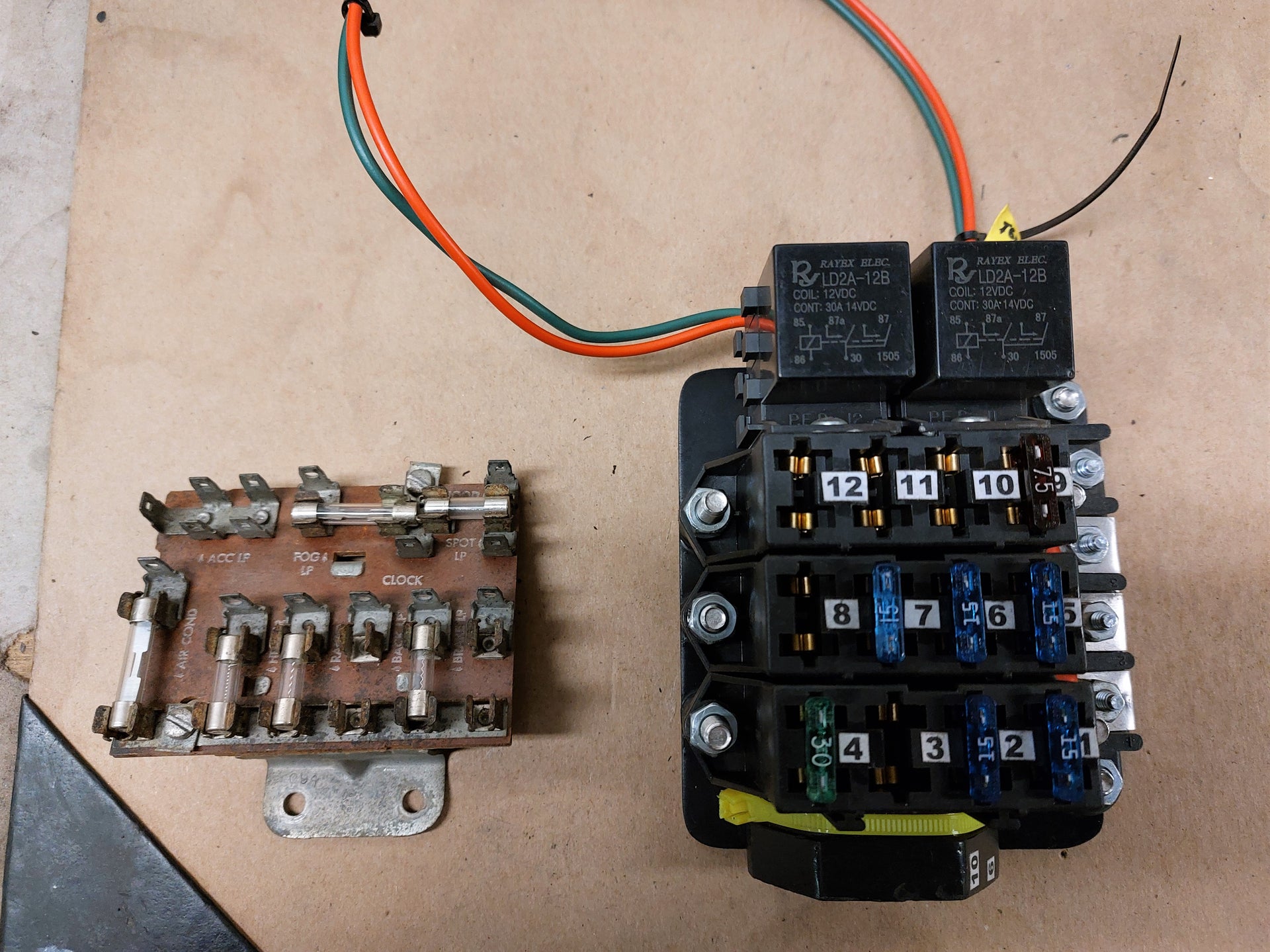
This is what I built compared to the original. I have it wired up so 4 circuits are always hot (1 - 4) 4 are hot in ignition switch position only (5 - 6) and 4 that are hot in accessory key position as well as the ignition position (9 - 12). The ignition and acc. circuits are powered through the relays at the top so there is less current going through the ignition switch. The green and red wires at the top are the trip wires for those relays.
At the bottom is where the circuits will connect to the fuse block. I made that out of the male half of a dozen female/male quick disconnect terminals that have the plastic over them to make a sealed connection. I super glued the 12 together after crimping 12 gauge wires into them. The I used epoxy meant for plastics to fill in between the terminals to form a solid block which I then tie wrapped to the base just below the fuse blocks. Everything is mounted to a base plate. On the left side is a terminal strip to bring in power and grounds.
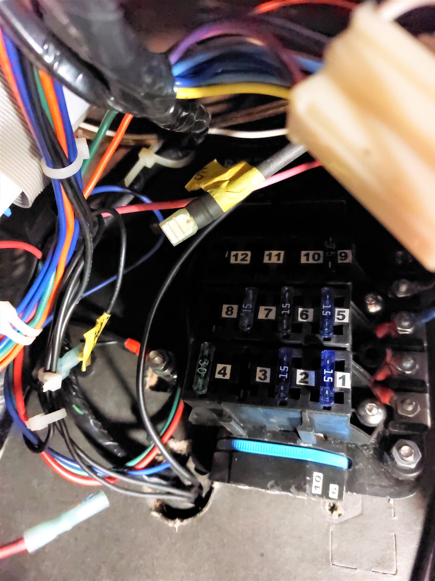
Hard to get a decent picture under the dash but here it is mounted in place ready to re-hook up all the wiring. I have it mounted just to the right and just below where the original fuse block was. This makes it a bit easier to get to the fuses and hook up the wiring without being to close to the clutch pedal. Just to the left of the #4 fuse position you can just see a bolt I put in one of the original fuse block mounting holes to use as a ground stud.
One thing I hadn't taken into account when I built the fuse block was a provision for the dash lights that are powered from the headlight dimmer switch. On the original fuse block five terminals in the upper left corner labeled ACC LP had 3 wires hooked to them. After some checking with my test light I figured out that one of the 3 was from the headlight switch dimmer control and the other 2 went out to the Dakota digital computer and the heater control panel lights. I was going to just add a buss bar type terminal strip but since I had an extra fuse block that I had room to clip onto the #1 - #4 fuse block I was the perfect solution. It just cleared my block for the incoming wires on the fuse panel so there wasn't room for the wires to come out the bottom of this one but that was easily solved by drilling a hole in the side to bring in the power connection from the headlight switch and the outputs to the lights. I only needed the 2 outputs for now so I left the fuses out of the unused ones. P.S. the terminals at the ends of the wires are the same type I used when I originally built the fuse panel. They are 1/4" male terminals and the female end they hook to have the same type of insulated covering so when you plug them together they are fully insulated.
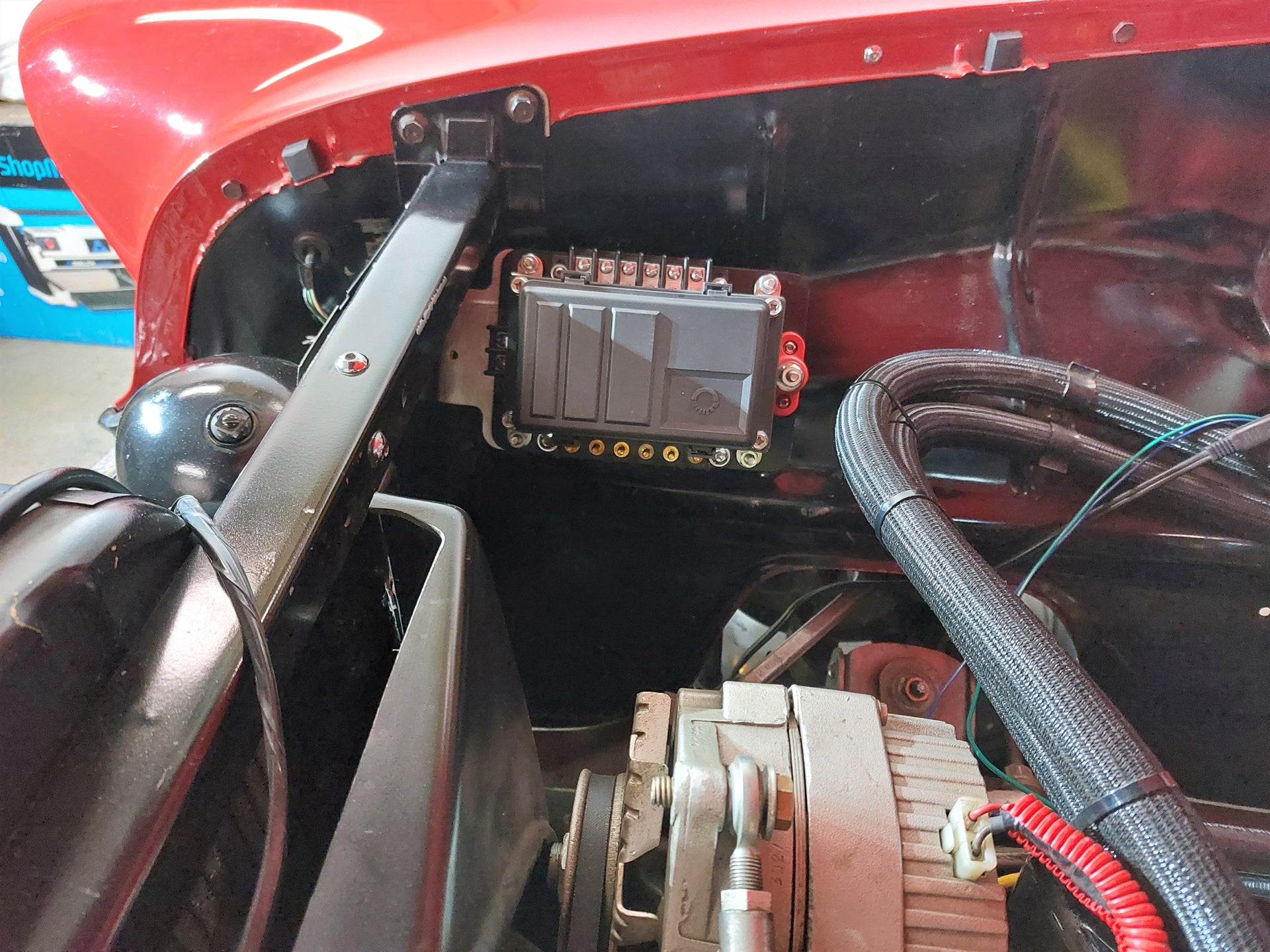
So with everything hooked up under the dash and checked to make sure it all works I stared work on installing the relay box that I purchased on Amazon. It has provisions for 6 relays and 6 fuse positions to feed power to the relays.
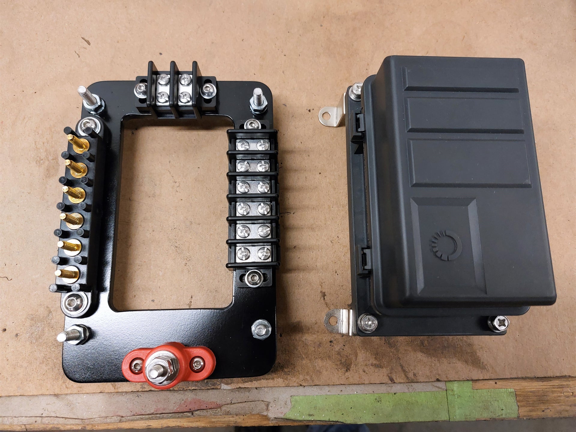
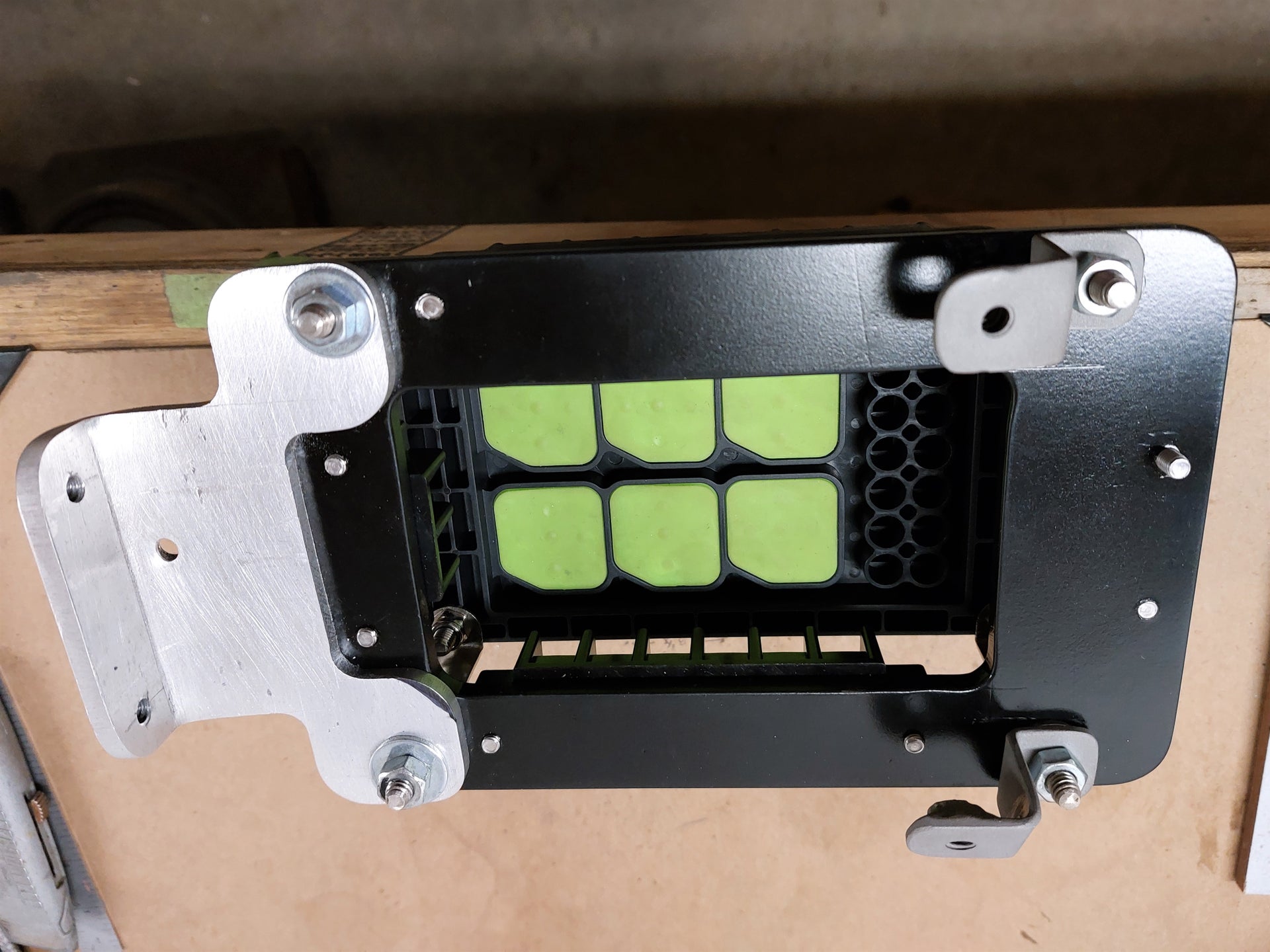
It has a water proof seal on the cover and seals where all the wiring goes in from the bottom. On the left is the mounting plate I made from 1/4" aluminum to mount the box to and wire terminals for the input triggers, ground connections, relay power outputs and the single stud for the main power input. The brackets on the relay box came with it but I did re-bend them so it would mount more to my liking.
Here is a shot of the box on the bracket. This side is where the relay trigger wires will hook up.
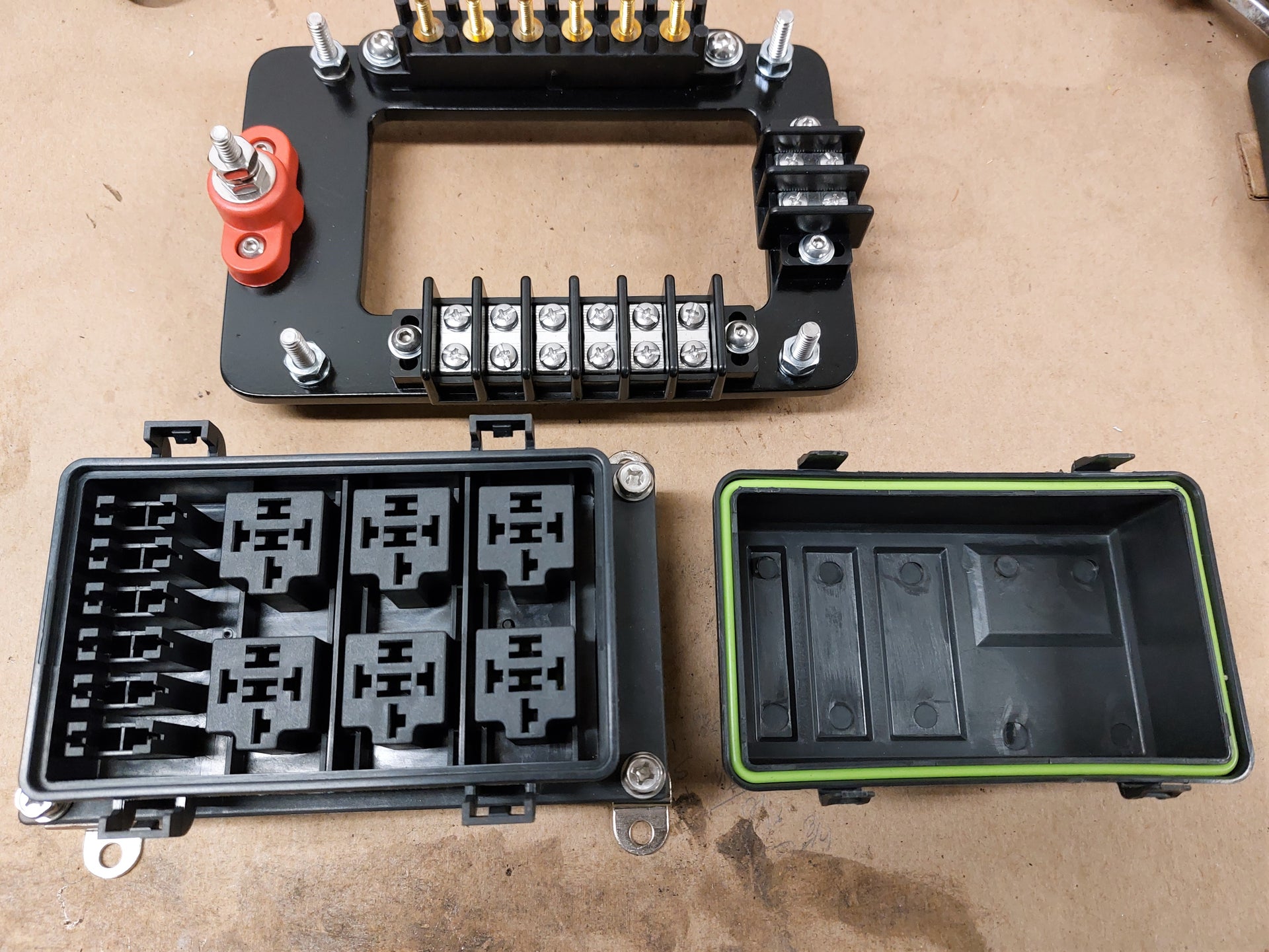
Here is a shot of the box with the cover off ready to start wiring it up.
Before I wired it up though I had to make brackets to mount it to the car. I decided on the passenger side by the core support as it was either this side or the drivers side. Since the power feed wires would be shorter on this side and my alternator is on the passenger side as well figured it would be as good a place as any. Some of the relay trigger wires will be longer this way but they are much smaller wires with way less current draw. The output wires from the relays go to both sides of the car anyway (headlights, horns and cooling fans) so it make no difference for those.
Here is a shot of the brackets to bolt the whole thing into the car. The aluminum bracket on the left end will bolt into the filler panel and the 2 small brackets on the right will bolt into the inner fender. Those were a bit tricky to make as the relay box base and the inner fender were not at the same angles. In this view you can see the seals where the relay wiring goes.


 Reply With Quote